

GTEM cells for radiated emissions: when they make sense
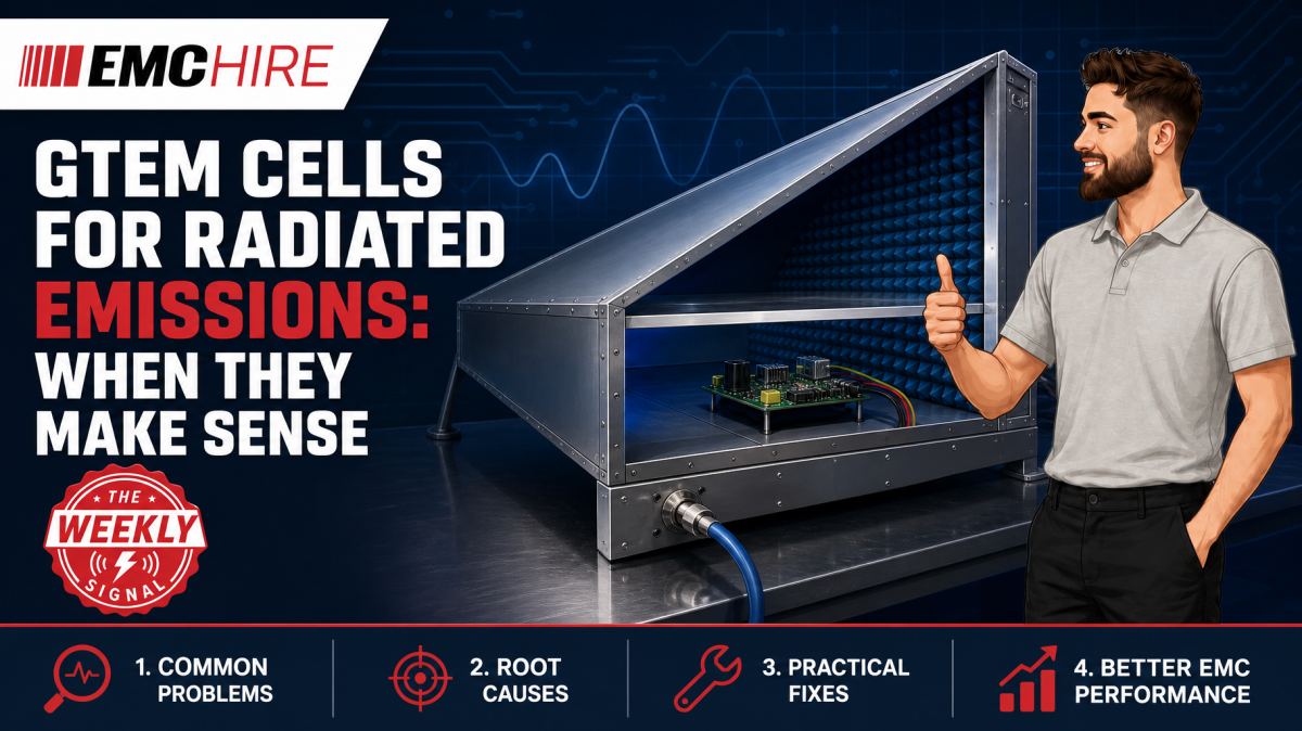
A GTEM cell can expose an emissions problem within minutes, but only if the EUT, cabling and measurement method fit the cell. Put an electrically large or poorly controlled installation inside it and the clean-looking plot may be misleading.
What a GTEM cell actually measures
A gigahertz transverse electromagnetic, or GTEM, cell is a tapered, shielded transmission structure designed to support a predominantly transverse electromagnetic mode over a broad frequency range. A central septum forms one conductor, with the enclosure acting as the return. Absorbing material and resistive loading at the tapered end reduce reflections and suppress unwanted modes.
For radiated emissions work, energy produced by the equipment under test, or EUT, couples into the cell and is measured at its RF port using a suitable receiver or spectrum analyser. Measurements are normally taken with the EUT in multiple orthogonal orientations because a single position cannot adequately represent every polarisation or radiation direction.
The resulting data is not automatically equivalent to an open-area test site, semi-anechoic chamber or fully anechoic room measurement. A conversion or correlation method is needed, together with knowledge of the cell geometry, validation data and applicable test procedure. IEC 61000-4-20 describes emissions and immunity testing in transverse electromagnetic waveguides, including TEM and GTEM structures. The current edition, product standard and any customer-specific test plan must be checked before deciding whether the method is acceptable.
This distinction matters. A GTEM cell is a controlled electromagnetic environment, not a small chamber with interchangeable results.
Where a GTEM cell makes engineering sense
Compact EUTs with controlled auxiliary equipment
GTEM cells are particularly useful for compact EUTs such as embedded controllers, sensor modules, small power converters, communications products and populated circuit assemblies. The EUT must fit within the cell's usable test volume without approaching the septum, floor or side walls too closely.
Physical fit alone is not enough. The product and its representative cable arrangement must remain electrically small enough for the intended method and frequency range. A small enclosure with a two-metre unscreened cable is no longer a compact radiating system. The cable may dominate the result, interact with the cell boundaries and change position between orientations.
The manufacturer's characterised uniform area, maximum EUT dimensions and loading limits should be treated as measurement constraints rather than convenient suggestions. Excessive EUT volume or conductive mass perturbs the field distribution and cell impedance. That can produce standing-wave effects, reduced repeatability and results that do not correlate sensibly with another test environment.
Rapid comparison during development
A GTEM cell is strongest as a repeatable pre-compliance and diagnostic tool. Engineers can compare PCB revisions, clock settings, enclosure treatments, filter components and cable terminations without waiting for chamber access. The shielded enclosure also reduces ambient signals, which makes low-level changes easier to interpret than measurements made with an improvised antenna in an ordinary workshop.
Relative measurements are often more useful than premature pass or fail declarations. If a revised common-mode choke reduces a repeatable spectral feature in all relevant EUT orientations, that is sound development evidence. If the result changes only after the cable has been moved, the apparent improvement may belong to the test setup rather than the design.
For products intended for CE or UKCA marking, early calibrated measurements can support design decisions and the technical file. They do not, by themselves, establish conformity. The manufacturer or responsible economic operator must identify the applicable legislation, product or product-family standard, limits, operating modes, conformity assessment route and documentation obligations. EMC Hire provides further guidance on EMC testing for CE marking.
Limited laboratory space
A GTEM cell occupies less space than a conventional radiated emissions facility and provides useful shielding from the local RF environment. This can make it practical for development laboratories that cannot accommodate a compliant test distance or absorber-lined chamber.
Space efficiency does not remove the need for disciplined operation. The cell requires suitable RF instrumentation, low-loss interconnection, controlled cable entry, safe power provision and a documented method. Its shielding performance can also be compromised by poorly closed access panels, damaged RF gaskets or unfiltered external connections.
Limits that affect equipment selection
The uniform area is finite
The usable test volume depends on the individual GTEM cell, frequency, septum height and validation method. There is no universal product size that is suitable for every cell. Obtain the manufacturer's dimensional and field-validation information, then assess the complete EUT configuration rather than the enclosure alone.
For immunity testing, uniformity concerns the applied field over a defined area. In emissions testing, the same physical restrictions still matter because a large EUT disturbs propagation and couples differently to the septum and enclosure. Do not assume that passing through the access door proves suitability.
Cables can become the main antenna
External power, Ethernet, sensor and actuator cables need representative routing and termination. A cable laid against the cell floor will couple differently from one suspended near the septum. Coiling excess length creates another unrepresentative structure and can suppress or enhance particular frequencies.
Where auxiliary equipment must remain outside the cell, feedthroughs should preserve the intended cable and shielding arrangement without creating an unintended RF path. Fibre-optic control is often useful where the product permits it. Any filtering added at the boundary must not alter the EUT port behaviour being investigated.
Correlation requires evidence
GTEM-derived emissions data may be processed to estimate an equivalent radiated result, but uncertainty arises from EUT directivity, polarisation, orientation, cell characteristics and the conversion algorithm. Correlation should be established against the intended formal method using representative products or known sources where practicable.
A fixed correction factor applied to every product is rarely defensible. A compact digital controller and a cabled power drive may have completely different radiation mechanisms. Product standards can also prescribe a conventional antenna test at a defined distance, making GTEM data valuable for pre-compliance while unsuitable as the final evidence required by that standard or contract.
IEC 61000-4-21 concerns reverberation chamber methods. It is relevant when comparing alternative radiated test environments, but a reverberation chamber and GTEM cell use different field-generation and measurement principles. Results and validation procedures must not be treated as interchangeable.
Typical scenario
Consider an illustrative compact controller containing a switching regulator, microprocessor and several external sensor ports. The team has limited laboratory space and wants to identify radiated emissions risks before booking formal testing.
A suitable setup could use a characterised GTEM cell, an emissions receiver or analyser with appropriate frequency coverage, calibrated RF cabling and software or documented calculations for the selected method. The controller would operate in its highest-emission representative modes, with realistic loads and communications activity. Multiple orthogonal orientations would be measured while cable routing, support material and auxiliary equipment remained controlled.
The engineering team must decide whether the controller and its cables fit the usable volume, whether external support equipment can be isolated adequately, and whether the required frequency range falls within the characterised capability of the complete system. Receiver detector and resolution bandwidth settings must follow the applicable method or development test plan. Peak detection is useful for fast exploratory scans, while quasi-peak or average detection may be required for comparison with particular emissions limits. One detector setting is not valid for every frequency range or standard.
If the wrong cell is selected, product loading may distort the measurement. If the team treats exploratory peak data as a formal quasi-peak result, it may either redesign unnecessarily or overlook a genuine margin problem. Early investigation still has strong value: dominant clock harmonics, cable common-mode currents and enclosure leakage can be identified while PCB, filtering and mechanical changes remain affordable.
EMC Hire can support this work through equipment selection, EMC pre-compliance testing, test facility access and on-site testing. Where a GTEM method is unsuitable, a conventional radiated emissions measurement system or formal test facility may provide more representative evidence. Power-port noise should be investigated separately using an appropriate conducted emissions system, including a suitable LISN where the applicable method requires one.
When to Hire EMC Equipment
Hiring a GTEM cell and associated instrumentation makes sense when the demand is tied to a development phase rather than a continuous laboratory workload. It gives the team access to an appropriately sized cell, receiver and accessories for a defined test window without committing capital to equipment that may not suit the next product programme.
Ownership carries more than the purchase cost. Storage space, RF cable condition, cell maintenance, receiver calibration, software support and periodic system checks all require management. A cell selected for today's small controller may be unusable for next year's larger cabled assembly.
Rental can also cover project peaks, allowing parallel debugging while another prototype is undergoing formal testing. Test equipment supplied by EMC Hire uses calibration traceable through an appropriate ISO/IEC 17025 accredited calibration provider where calibration is relevant to the measurement. Suitable traceable calibration supports repeatability, confidence in recorded data and more meaningful comparison between development and formal measurements.
Hiring is less attractive when the method itself has not been defined. Before requesting equipment, establish the EUT dimensions, cable configuration, required frequency coverage, likely product standard, measurement objective and available RF expertise. Otherwise, the project can lose several days assembling a technically tidy but irrelevant setup.
Common EMC Testing Mistakes to Avoid
Testing only one EUT orientation
A single orientation favours particular coupling paths and polarisation. It can miss a dominant emission from another face of the product, creating false confidence. Record every orientation and use a repeatable fixture made from suitably low-permittivity material.
Ignoring cable position
Cable movement changes common-mode current distribution and coupling to the cell. If routing is not photographed and dimensioned, a later test may not reproduce the original result. Avoid arbitrary coils and keep representative terminations connected.
Overloading the usable volume
Placing a large conductive EUT too close to the septum changes the local field and impedance. The resulting resonances may belong to the loaded cell rather than the product. Check cell loading restrictions and leave the specified clearances.
Using analyser settings copied from another test
Incorrect resolution bandwidth, detector or dwell time can change the indicated amplitude, particularly for intermittent or modulated disturbances. Settings must match the applicable frequency range and method. A fast peak scan is a diagnostic tool, not automatically a compliance measurement.
Failing to capture EUT operating modes
An idle processor, inactive radio interface or unloaded converter can produce a reassuring but unrepresentative plot. Record firmware version, traffic state, loads, power conditions and cycle timing. Automated mode sequencing can improve coverage, provided the receiver observes each state for long enough.
Treating GTEM data as universally equivalent to chamber data
Without a justified conversion method and correlation evidence, direct comparison can lead to false failures or missed risks. Keep raw readings, correction data, cable details, photographs and processing steps. Weak records leave the technical file with an evidence trail that another engineer cannot reproduce.
Frequently Asked Questions (FAQs)
Can a GTEM cell replace formal radiated emissions testing?
Sometimes a specified method may permit TEM waveguide measurements, but many product standards or contractual plans require another test environment and defined distance. Check the latest active standard, product scope and customer requirements. GTEM measurements are commonly most useful for pre-compliance, diagnosis and design comparison.
How small must the EUT be?
There is no single limit. Suitability depends on the cell geometry, characterised test volume, frequency, conductive loading and complete cable arrangement. Use the cell manufacturer's validated dimensions and the selected test method rather than a generic enclosure-size rule.
Can the same GTEM cell perform immunity testing?
Many GTEM systems can support radiated immunity work using suitable RF generation, amplification, monitoring and field calibration. That is a different measurement chain from emissions testing. Required field strength is expressed in V/m, while radiated emissions results are commonly expressed in dBµV/m after the applicable processing.
Should we use a spectrum analyser or an EMI receiver?
Either may support development measurements if its frequency coverage, dynamic range, overload performance, detectors and bandwidths suit the test plan. An EMI receiver designed for CISPR measurements is generally preferable where standards-based detector behaviour is required. Protect the input and account for cable loss and any external attenuation.
Does a quiet GTEM plot prove the product will pass?
No. It improves confidence only to the extent that the setup represents the final product and correlates with the required method. Installation cables, enclosure changes, production tolerances and different operating modes can all alter emissions.
What records should be retained?
Keep instrument identification and calibration status, cell configuration, raw and processed data, correction factors, photographs, cable dimensions, EUT orientations, software version, operating modes, environmental details and the test plan. These records support engineering review, gap analysis, mitigation evidence and a more defensible compliance trail.
Choosing the right route
A GTEM cell earns its place when the EUT is compact, the setup is controlled and the objective is clear. It offers fast feedback, good shielding and repeatable comparison without occupying a full chamber. Its limits become significant when cables dominate, the EUT heavily loads the cell or the final standard requires a conventional radiated test method.
EMC Hire can help assess whether a GTEM setup, hired radiated emissions system, on-site investigation or test facility booking is the better route. Support can extend from early debugging through formal compliance testing where appropriate, without implying certification or guaranteed conformity. For defence, automotive and aerospace programmes, pre-compliance work can reduce redesign risk, although final evidence may need to come from an appropriately accredited laboratory under the applicable contract or programme.
To discuss equipment hire, pre-compliance support, formal compliance testing, on-site testing or space at the EMC Hire test facility, contact the engineering team on +44 (0)1462 817111 or email sales@emchire.co.uk. Bring the EUT dimensions, cable schedule, target markets and proposed standards to the first discussion. Those details usually determine whether a GTEM cell is the right tool.
Disclaimer: Content is for informational purposes only and does not constitute formal engineering or regulatory advice. Always verify testing procedures against current official standards (e.g., ISO, MIL-STD, DEF STAN). EMC Hire Limited accepts no liability for outcomes resulting from the use of this information.