

Medical device radiated immunity planning
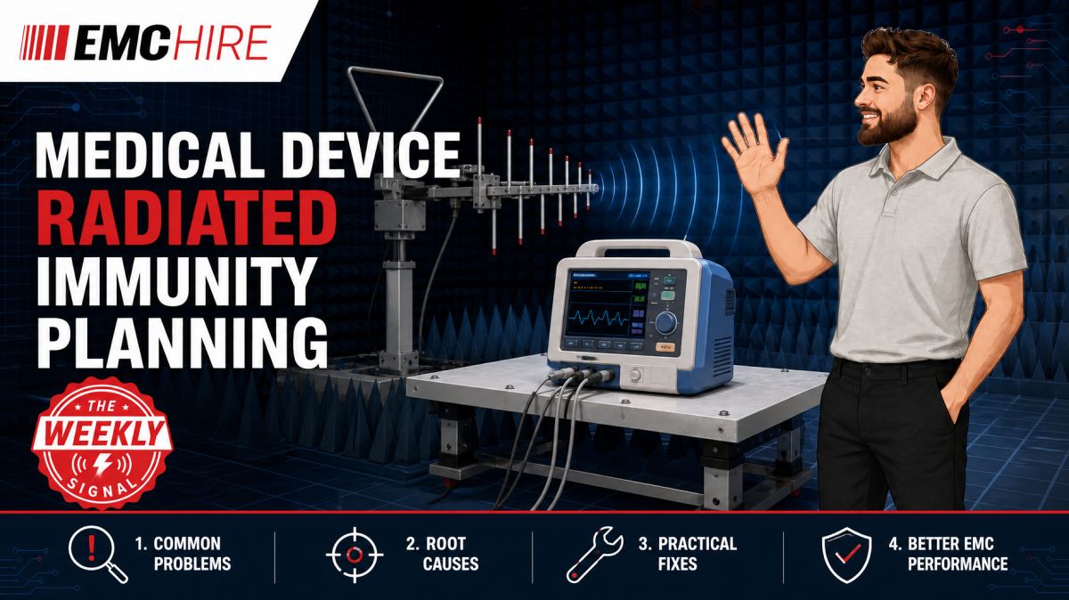
A medical device can remain powered throughout a radiated immunity test and still fail. The harder question is whether RF exposure caused an unacceptable clinical performance change that the monitoring system failed to capture.
Start with the applicable medical product requirements
Medical radiated immunity planning should begin with the device's intended use, intended environment and applicable product standards, not with the signal generator frequency range. For medical electrical equipment, IEC 60601-1-2 is commonly relevant alongside the IEC 60601-1 general safety and performance framework. Particular standards may modify or add requirements for a specific product type.
IEC 61000-4-3 provides the basic radiated RF electromagnetic field immunity test method. It describes the general test approach, including field generation, calibration and exposure. It does not, by itself, determine every test level, frequency range, performance criterion or configuration applicable to a medical product. Those decisions normally come from the product or product-family standard, the equipment's intended electromagnetic environment and the manufacturer's risk management work.
Check the latest active editions and amendments before fixing the test plan. Confirm the applicable frequency ranges, field strength, modulation, dwell time, frequency step, antenna polarisation, exposure faces, operating configurations and performance criteria. Customer specifications and market-specific requirements may also affect the programme.
This matters because copying a setup from a previous product can produce a technically tidy but irrelevant test. A professional healthcare product, home healthcare device and equipment intended for a special environment may not share the same immunity assumptions. Radio-frequency proximity fields from nearby wireless transmitters may also require separate consideration under the applicable medical standard.
Define performance before applying the field
Pass and fail criteria must be written before testing begins. Otherwise, engineers tend to judge unexpected behaviour during the test, when RF exposure, chamber access restrictions and limited diagnostic information make objective decisions difficult.
For medical equipment, a reset is not the only meaningful failure. Potentially relevant effects include corrupted measurements, delayed alarms, unintended actuator movement, interruption of therapy, incorrect display values, loss of communications, degraded sensor accuracy or a transition into an unsafe operating state. A temporary deviation may be acceptable in one function and unacceptable in another, depending on the product standard and the manufacturer's risk analysis.
Define what will be observed, the permitted deviation, the observation method and the required recovery behaviour. Include any performance that cannot be monitored directly during exposure. If the product records internal data, decide how those records will be time-correlated with frequency, field level and EUT state.
A simple camera aimed at a display may miss a short alarm suppression or transient numerical error. Conversely, an electrically connected monitoring lead can become an unintended receiving antenna and change the immunity of the equipment under test. Fibre-optic links, shielded filtering arrangements or chamber-compatible optical monitoring often provide a less intrusive route, but their effect on the real clinical configuration still needs assessment.
Field uniformity is not the same as EUT exposure
IEC 61000-4-3 testing relies on a calibrated uniform field area. That calibration establishes the relationship between the test system and the required field under defined conditions. Once a large EUT, support table, cables and auxiliary equipment are introduced, scattering and loading alter the local electromagnetic environment.
The test laboratory therefore needs an appropriate calibrated field arrangement and sufficient amplifier margin to maintain the specified test level. Driving an amplifier into compression can distort the modulation and create harmonics, so indicated forward power alone is not proof that the intended field has been applied correctly.
Field probes must be suitable for the frequency range and field strength. Their isotropic response, linearity and calibration uncertainty influence confidence in the result. Test equipment used by EMC Hire is calibrated with traceability through an appropriate ISO/IEC 17025 accredited calibration provider. Suitable traceable calibration supports repeatability, confidence in recorded data and comparison between development work and formal testing. It does not remove uncertainty caused by poor EUT configuration or monitoring.
Test distance, antenna height and antenna-to-EUT alignment must follow the selected method and validated chamber arrangement. Moving the antenna closer because the amplifier cannot reach the requested field is not an innocent adjustment. It changes field distribution, coupling and the relationship to the established uniform field area.
Antennas, amplifiers and frequency coverage
No single antenna should be assumed to provide efficient, well-controlled coverage across every required frequency. The antenna type, gain, voltage standing wave ratio, power handling and beam characteristics must suit the validated range and chamber geometry. EMC Hire can support selection from its HF and VHF antenna options, while antennas and near-field probes can also assist development-stage investigation. Near-field probes are diagnostic tools and are not substitutes for calibrated radiated immunity exposure.
Amplifier selection requires more than checking nominal output power. Cable loss, antenna mismatch, modulation headroom, chamber loss and the power needed at the least efficient frequencies all matter. A system that reaches the target field at mid-band may run out of margin near an antenna transition or band edge.
Where antennas or amplifiers change during a sweep, define the crossover frequencies and verify that coverage remains continuous. An undocumented gap can leave a susceptibility untested. Excessive overlap can also expose the product differently if two antenna systems produce materially different field distributions.
Operating modes and cable configurations
Medical products rarely have one worst-case operating mode. A patient monitor may have maximum channel activity in one mode, maximum display and processor loading in another, and its most sensitive analogue path in a third. A pump may be more susceptible while driving a motor than while idle, but alarm handling and communication states also need examination.
Select operating modes using functional analysis and electromagnetic risk, rather than simply running a demonstration sequence. Exercise safety-related functions, representative sensor inputs, wireless interfaces, alarm states, battery charging and connected accessories where applicable. Automated cycling can improve coverage, provided the dwell time at each frequency is long enough for the susceptible function to occur and for the monitoring system to detect it.
Cable type, length, termination and routing can dominate coupling below and around resonance regions. Use configurations permitted by the manufacturer and representative of intended use. If several cable layouts are possible, identify those most likely to couple energy into sensitive ports. Neatly coiling spare cable to fit the chamber may create an inductive structure that bears little resemblance to the installed product.
Support equipment outside the chamber must not mask failures or introduce its own. Simulators, loads and communications interfaces should be documented, checked for immunity where necessary and arranged so that their cables do not bypass the intended test boundary.
Typical scenario
Consider an illustrative mains-powered medical controller with analogue patient-connected inputs, Ethernet, an external alarm output and an internal radio. The compliance team needs to plan radiated RF immunity before design verification.
The first decision is scope. The team reviews IEC 60601-1-2, the relevant particular standard, intended professional healthcare environment, radio functions and risk management records. It defines unacceptable performance in measurable terms, including alarm delay, analogue channel error, loss of control output and recovery after exposure.
The likely setup uses a suitable chamber, calibrated field probe, signal generator, power amplifiers and antennas covering the required bands. The controller is exercised in several operating modes, with representative sensors and accessories. Fibre-optic monitoring is considered for internal measurements because long copper diagnostic leads could create an artificial RF coupling path.
If the team chooses an amplifier from headline wattage alone, it may not maintain the required field strength across the complete sweep. Selecting an unsuitable antenna can create poor efficiency or inadequate coverage. Running only the normal display mode could miss susceptibility during alarm generation or radio transmission.
Early pre-compliance work allows the engineers to identify sensitive faces, cables, frequencies and operating states while PCB, enclosure and filtering changes remain practical. A susceptibility can then be investigated using controlled substitution, cable current measurements and localised diagnostic injection. These development measurements do not prove compliance, but they reduce the chance of discovering a system-level weakness during formal testing.
EMC Hire can support this work through equipment hire, practical setup guidance, on-site testing, accessible pre-compliance investigation and bookings at its test facility. Formal compliance testing may also be available where appropriate for the selected conformity route. The manufacturer remains responsible for confirming applicable legislation, standards and documentation requirements.
When to Hire EMC Equipment
Hiring is technically attractive when radiated immunity demand is irregular or tied to a defined design-verification window. A complete system may require generators, amplifiers, directional couplers, power monitoring, field probes, antennas, control software and chamber access. Buying one component without checking system compatibility can leave an expensive capability gap.
Rental avoids unnecessary capital expenditure and allows equipment to be matched to the required frequency bands, field strength and test geometry for the current programme. It can also cover short-term project peaks when an internal system is already committed or lacks sufficient amplifier power.
Ownership brings calibration planning, servicing, storage and periodic functional verification. RF power amplifiers and field probes can remain unused for long periods while still generating maintenance overhead. Hiring transfers much of that equipment ownership burden and reduces the risk of buying a system that proves unsuitable for later programmes with different frequencies or test levels.
For medical compliance teams, the strongest approach is often mixed. Hire equipment for early engineering work or on-site investigation, then use a controlled facility for pre-compliance and formal testing. This produces calibrated engineering data, improves comparison between test stages and supports a more defensible technical file, Declaration of Conformity and self-certification process where legally and technically applicable. Testing alone does not complete the manufacturer's conformity obligations.
Common EMC Testing Mistakes to Avoid
Treating the standard level as the whole test plan
Field strength is only one parameter. Incorrect modulation, frequency stepping, dwell time, antenna polarisation or exposure-face selection can leave real susceptibilities undiscovered and produce an unsuitable evidence trail.
Using convenient rather than representative operating modes
An idle EUT may pass because sensitive analogue conversion, motor drive or alarm processing never occurs during exposure. Record software versions, modes, loads, simulated inputs and activity sequences so the test can be reproduced.
Changing cable routing without recording it
A movement of a few tens of centimetres can alter common-mode coupling and resonant behaviour. Photographs, cable lengths, termination details and accessory part numbers are needed if a failure must later be reproduced.
Monitoring through intrusive copper connections
Diagnostic leads can increase susceptibility, suppress it by changing return paths, or carry RF into external instrumentation. Monitoring arrangements should be assessed as part of the EUT configuration, not treated as electrically invisible.
Ignoring amplifier compression and antenna transitions
A power reading can appear stable while the amplifier waveform is distorted. Poorly planned band transitions may also create frequency gaps. Verify system margin, forward and reflected power behaviour, and validated antenna coverage before exposing the EUT.
Writing the report after the configuration has been dismantled
Missing EUT modes, cable positions, antenna details, dwell parameters or observed deviations make later diagnosis difficult. They also weaken technical documentation and prevent meaningful comparison with retests.
Frequently Asked Questions (FAQs)
Does passing IEC 61000-4-3 demonstrate medical device compliance?
Not by itself. IEC 61000-4-3 is a basic immunity test method. The applicable medical product standards, particular standards, risk management, performance criteria and conformity route determine how the result is used.
How should the required field strength be selected?
Use the applicable edition of the medical product standard, intended electromagnetic environment and any particular or contractual requirements. Do not select a level from a previous product without confirming that its scope, use environment and performance assumptions match.
Must every operating mode be tested?
Not necessarily, but the selected modes must provide defensible coverage of the functions and states most relevant to electromagnetic risk. Mode grouping may be justified where configurations are electrically equivalent, provided the reasoning is documented.
Can open-area testing replace a chamber?
Radiated immunity requires controlled field generation, personnel protection and management of external radio services. A suitable chamber is normally the practical route for repeatable testing at significant field strengths. Any alternative arrangement must satisfy the applicable method, safety controls and regulatory restrictions on RF transmission.
Can near-field probes identify a radiated immunity weakness?
They can help localise sensitive circuitry during debugging, particularly around clocks, analogue front ends, cables and enclosure apertures. Probe injection is not equivalent to the calibrated far-field exposure used for formal radiated immunity testing.
What evidence should be retained?
Keep the approved test plan, standards and editions used, EUT identification, software and operating modes, accessory configurations, cable layouts, photographs, monitoring criteria, equipment records, calibration traceability, test parameters, observations and deviations. These records support repeatability, the technical file and later engineering review.
Planning the next test window
EMC Hire supports medical device EMC compliance planning and practical testing for a range of medical devices. Support can include equipment selection, hire, pre-compliance engineering, on-site testing, formal compliance testing where appropriate and access to EMC test facilities.
Before committing chamber time, discuss the applicable standard, EUT dimensions, required field strength, frequency coverage, cable interfaces, operating modes and monitoring arrangements with the EMC Hire engineering team. This usually exposes setup limitations while they can still be corrected.
To request an equipment hire quotation, arrange on-site testing, discuss pre-compliance or formal compliance work, or book space at the EMC Hire test facility, call +44 (0)1462 817111 or email sales@emchire.co.uk.
Disclaimer: Content is for informational purposes only and does not constitute formal engineering or regulatory advice. Always verify testing procedures against current official standards (e.g., ISO, MIL-STD, DEF STAN). EMC Hire Limited accepts no liability for outcomes resulting from the use of this information.