Current Probes / Clamps / LISNs / CDNs
EMC Hire provide a range of Conducted Emissions Test Equipment in three general subsections under the general title Electromagnetic Transducers-Conducted.
EMC Hire provide a range of Conducted Emissions Test Equipment in three general subsections under the general title Electromagnetic Transducers-Conducted.
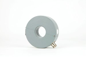
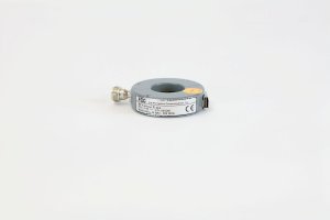
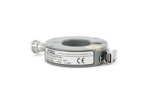
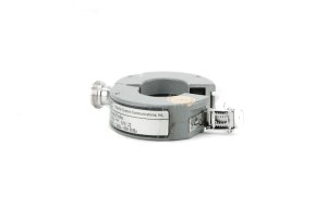
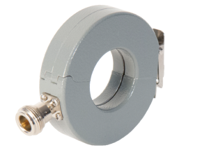
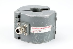
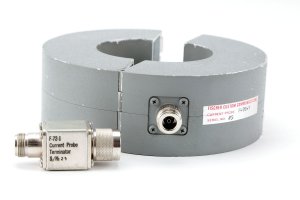
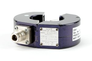
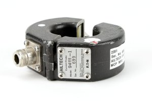
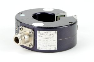
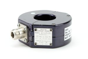
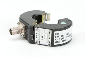
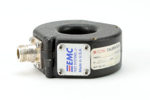
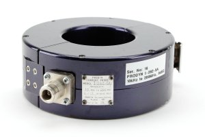
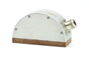
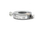
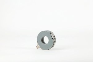
A current clamp is used to measure the amount of current flowing, without the need to break into the conductor. The cable is passed through the centre of the current probe, which then acts as the secondary winding of a current transformer, with the cable under test forming the primary.
A current probe can also be used to inject RF signals onto a cable, by inducing a current onto the cable under test.
Our wide range of Current Probes and Clamps are simple to use and highly accurate, providing engineers with options to measure a broad range of RF currents using a clamp-on function.
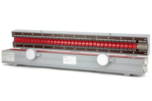
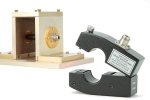
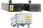
LISNs are used to test conducted and radiated radio-frequency emissions and susceptibilities by acting as a low-pass filter usually placed between an AC or DC power supply and the equipment being tested.
Different types of LISNs can be used to measure DC, single phase or 3-phase AC power connections.
LISNs create a measurable and known impedance and radio frequency measurement port, which allows engineers to assess other impedances or susceptibilities.
Selecting the correct LISN for the required application is based on the following parameters:
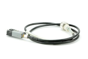
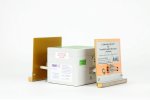
CDNs are primarily used for RF Conducted Immunity testing purposes by inserting disturbances to Equipment under Test (EuT). A CDN is a combination of a Coupling Network and a Decoupling Network.
Coupling Networks inject the signal onto unscreened, shielded, balanced and coaxial cables and power mains. Decoupling networks are used to ensure that the disturbance signal does not influence the auxiliary equipment and is placed between the EuT and the auxiliary equipment.
If you have any questions about any of our Current Probes, Clamps, LISNs or CDNs, please contact us or give us a call on +44 (0) 1462 817111 to speak to an expert.
Find out more about EM Transducers Conducted (200's)