


ISO 11452-2 absorber-lined chamber testing explained
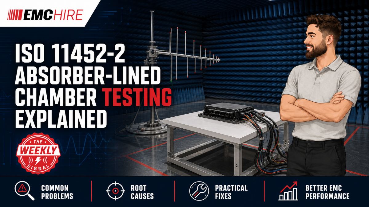
A vehicle component can survive the specified field strength and still produce misleading ISO 11452-2 results if its harness, antenna geometry or operating mode is poorly controlled.
Absorber-lined chamber testing is not simply a matter of placing an electronic control unit in a screened room and transmitting RF energy towards it. The chamber, field-generation system, wiring harness, support equipment and monitoring method form one measurement system. Small departures from the defined arrangement can change the RF coupling path enough to obscure a genuine susceptibility or create one that will not be repeatable elsewhere.
What ISO 11452-2 testing is intended to establish
ISO 11452-2 is a component-level radiated immunity test method for electrical and electronic vehicle components. It uses an absorber-lined shielded enclosure, commonly described as an ALSE, to expose the equipment under test, or EUT, and its associated wiring to a controlled electromagnetic field.
The method is intended to assess whether a component continues to perform as required when subjected to narrowband radiated electromagnetic disturbances. Such disturbances may originate from broadcast services, mobile communications, vehicle transmitters and other RF sources. It is an immunity test. It does not define radiated emissions limits, and the chamber setup should not be confused with a radiated emissions measurement system.
ISO 11452-2 is part of the wider ISO 11452 vehicle component immunity test family. Different parts use different coupling mechanisms, so selecting Part 2 should follow the applicable vehicle manufacturer specification, component requirement or agreed validation plan rather than convenience alone.
The published method covers a broad RF range, but the actual frequencies, field strengths, dwell times, modulation and performance criteria depend on the current edition, the device being assessed and any customer-specific requirements. Engineers should verify the latest active edition and amendment status directly with ISO or the relevant standards supplier. OEM specifications can add frequency bands, test levels, monitoring requirements and failure classifications beyond the base method.
Why the absorber-lined chamber matters
A conductive enclosure contains the transmitted RF energy and reduces interference from external radio services. Absorber is then used to suppress reflections from selected chamber surfaces. Without adequate absorption, incident and reflected waves create standing-wave patterns that can produce large spatial variations in electric-field strength.
Those variations matter. If the EUT occupies a field maximum during one test and a minimum during another, two apparently identical programmes can produce different functional outcomes. Chamber characterisation, antenna positioning and adherence to the prescribed geometry therefore influence repeatability as much as the nominal amplifier power.
An automotive ALSE setup is not automatically interchangeable with a commercial radiated immunity arrangement based on IEC 61000-4-3. The standards use different calibration concepts, geometries and equipment configurations. Treating an IEC uniform-field area as proof that an ISO 11452-2 setup is correct can leave the actual EUT and harness exposure inadequately characterised.
Field generation and calibration
The RF chain normally comprises a signal generator, modulation source where required, power amplifier, directional coupler or power monitoring arrangement, cabling and an antenna suitable for the frequency band. More than one antenna and amplifier may be needed to cover the required range. Each transition between RF paths must be controlled because gain compression, cable loss and poor antenna matching can cause the delivered field to depart from the requested level.
ISO 11452-2 uses a field calibration and substitution-based approach. The field is established at the defined reference position under the prescribed calibration conditions, and the associated forward power is recorded. During EUT exposure, the calibrated forward-power values are applied subject to the controls and limitations in the applicable procedure.
This is not permission to keep increasing amplifier output until a field probe placed beside the live EUT shows the target value. The EUT, harness and support structures disturb the field. Closed-loop levelling against a probe during the test can drive excessive power into the chamber and produce an exposure that no longer corresponds to the calibrated method.
Power amplifiers also need adequate linearity and headroom. Operating near saturation distorts amplitude modulation and invalidates the relationship between the calibrated carrier and the intended modulated waveform. Forward and reflected power monitoring helps identify an overloaded amplifier, antenna mismatch or configuration error, but acceptable limits must come from the test method and equipment ratings.
The wiring harness is part of the RF coupling path
For many vehicle components, the wiring harness is a more effective receiving structure than the enclosure. Its length, height above the reference ground plane, branch arrangement, termination and orientation determine the common-mode voltage and current delivered to EUT ports.
Coiling excess cable is particularly damaging to repeatability. A coil introduces inductive and capacitive coupling that is not representative of the defined harness geometry. Moving a branch by only a modest distance can also alter its relationship with the antenna polarisation and local field distribution.
The EUT case bonding arrangement deserves the same discipline. A component intended to be chassis-mounted should be bonded as required by the test plan, using a mechanically and electrically representative connection. An unnecessarily long bonding strap adds inductance, raising its RF impedance and changing enclosure current paths. Conversely, bonding an electrically isolated product directly to the ground plane may suppress the susceptibility mechanism that the test is meant to reveal.
Functional monitoring without creating another antenna
Vehicle components must be exercised in representative and technically demanding modes. A gateway should carry realistic network traffic. A motor controller may need active loads and speed or torque states. Sensor interfaces may require simulated signals near diagnostic thresholds. Testing an energised component in an idle state can miss failures that occur only while processors, converters or communications interfaces are active.
Monitoring cables can unintentionally change the result. Long copper oscilloscope, Ethernet or serial leads passing through the chamber couple RF into the EUT and may provide an artificial return path. Fibre-optic links, filtered feedthroughs and appropriately decoupled support equipment are generally preferable where the functional architecture permits them.
Performance criteria should be agreed before exposure begins. Engineers need objective definitions for acceptable deviation, temporary degradation, self-recovery, diagnostic trouble codes, communication errors and safety-related responses. A note stating that the unit “continued to operate” is rarely adequate evidence for a complex automotive function.
Typical scenario
Consider an illustrative body-control module being prepared for an OEM component validation programme. The module has several CAN and LIN interfaces, switched outputs and low-level sensor inputs. Its enclosure is electrically isolated in the vehicle, while the production harness runs alongside body metal for part of its route.
The engineering team must translate the contractual test specification into a workable ISO 11452-2 plan. Decisions include the required frequency bands, antenna changes, field levels, modulation, dwell strategy, harness arrangement, ground-plane relationship, load simulation and pass or fail criteria. They must also establish whether production-intent software, enclosure fixings and cable terminations are available.
If the prototype is tested with a shortened bench harness and laboratory loads mounted beside the enclosure, the coupling path will differ from the validation configuration. A susceptibility on a sensor line may disappear, giving false confidence. The reverse is also possible: an unterminated laboratory lead can resonate and create a failure that will not exist in the vehicle installation.
Early pre-compliance work in an accessible setup allows the team to investigate frequency-sensitive resets, communication errors and analogue deviations before the design is frozen. Current probes, near-field probes and targeted conducted immunity investigation may help identify the affected port, although those diagnostic methods do not replace the prescribed chamber test.
EMC Hire can support this work through equipment hire, practical setup guidance, pre-compliance engineering, on-site testing and access to test facilities. Formal compliance testing can then be planned where appropriate, with the configuration and monitoring evidence developed during debugging carried forward. For automotive programmes, final testing may need an appropriately accredited laboratory where this is required by the customer, contract or conformity route.
Interpreting the result and preserving evidence
A radiated immunity result is only defensible when it is tied to a controlled configuration. Records should identify the EUT hardware and software state, harness drawing, loads, support equipment, antenna, RF path, calibration data, test levels, modulation, dwell, monitored functions and observed responses. Photographs should show cable positions and bonding details clearly enough for another engineer to rebuild the arrangement.
Traceability also applies to the instrumentation. EMC Hire uses test equipment with calibration traceable through an appropriate ISO/IEC 17025 accredited calibration provider. Suitable traceable calibration supports measurement accuracy, repeatability and comparison between development and formal testing. It also strengthens the evidence available to engineering management, customers and reviewers. The accreditation relates to the calibration provider or calibration activity, not to the physical instrument itself.
Pre-compliance data can support design decisions, EMC risk assessments, mitigation records and a technical file where relevant, but it does not automatically demonstrate compliance. The manufacturer remains responsible for identifying applicable legislation, product standards, customer requirements, conformity assessment routes and documentation obligations.
When to Hire EMC Equipment
ISO 11452-2 systems require more than an RF generator and amplifier. Suitable antennas, directional power measurement, field probes, RF cabling, monitoring equipment and safety controls must work across the required bands and power levels. Buying a system for one programme can tie up capital in equipment that may not suit the next OEM specification.
Hiring is often technically and financially sensible when a project needs a defined frequency band or field level for a limited development window. It can also cover project peaks when an internal chamber is available but the normal amplifier chain is occupied, under repair or lacks sufficient bandwidth.
Rental avoids long-term storage, servicing and calibration overheads, while reducing the risk of purchasing an antenna or amplifier combination that cannot support future programmes. The proposed chain still needs engineering review. Amplifier power cannot be selected from field strength alone because chamber loss, antenna gain, cable loss, test distance, modulation headroom and mismatch all affect the required output.
For teams without a suitable ALSE, booking a facility or arranging supported testing may be more productive than assembling a temporary chamber. EMC Hire's automotive EMC support can be used for pre-compliance investigations, equipment selection, on-site work and planned compliance testing where appropriate.
Common EMC Testing Mistakes to Avoid
Using calibration data from a changed RF path
Replacing an antenna, cable, amplifier or connector after calibration changes the relationship between forward power and field strength. Reusing the old data can under-test the EUT or expose it beyond the intended level. Any configuration change should be assessed against the calibration requirements before testing continues.
Ignoring amplifier compression
A power reading can appear stable while the amplifier is compressing waveform peaks. The resulting modulation depth and spectral content may be wrong, making the exposure unrepresentative. Linearity and modulation should be checked at the operating power, not assumed from a small-signal gain figure.
Treating harness placement as approximate
Uncontrolled cable height, branching or termination changes induced common-mode currents. This produces poor laboratory-to-laboratory correlation and can move a susceptibility threshold enough to affect the recorded classification.
Allowing support equipment to mask failures
Slow monitoring may miss short resets or communication dropouts. Equally, poorly filtered monitoring leads can inject RF directly into an interface. The monitoring system requires its own immunity and bandwidth assessment.
Testing the easiest operating mode
An idle EUT may consume less current, generate fewer internal timing events and leave outputs inactive. Passing that mode says little about performance during demanding vehicle functions. Modes should be selected from functional and EMC risk, then documented.
Writing the report after dismantling the setup
Once harnesses and loads have been removed, undocumented details are difficult to reconstruct. Missing photographs, power settings, software versions or cable positions weaken repeatability and can leave an unsuitable evidence trail for an OEM review or later design change.
Frequently Asked Questions (FAQs)
Is ISO 11452-2 a vehicle-level test?
No. It is primarily a component test method for vehicle electrical and electronic equipment. Whole-vehicle radiated immunity uses different standards, facilities and configurations.
Can one antenna cover the complete test range?
Not necessarily. Antenna bandwidth, power handling, gain, chamber performance and the required field strength determine whether multiple antennas and amplifiers are needed. The complete RF chain should be assessed band by band.
Can the field probe remain beside the EUT during exposure?
The applicable ISO 11452-2 procedure should be followed. The substitution method relies on prior field calibration, and using a probe for closed-loop field control beside the EUT may alter the prescribed exposure. A probe may still have diagnostic or safety uses where these do not conflict with the method.
Does passing ISO 11452-2 prove that a component is compliant?
Not by itself. The result addresses one radiated immunity method under a defined configuration. Product requirements may also include conducted immunity, transient immunity, electrostatic discharge, emissions and OEM-specific tests. The responsible organisation must confirm the complete compliance route.
How should an OEM specification be handled alongside ISO 11452-2?
Read both documents before writing the plan. The OEM document may alter test levels, modulation, frequency steps, dwell, harness layout, functional status classification and reporting. Conflicts or ambiguities should be resolved with the approving authority before testing, not after a disputed result.
Can pre-compliance testing use non-production hardware?
Yes, if the limitations are recorded and understood. Early hardware can expose coupling mechanisms before tooling and software are frozen, but changes to enclosures, connectors, grounding, filters or harnesses may materially change the final result.
Discussing an ISO 11452-2 programme
Before committing chamber time, confirm the current standard edition, OEM specification, test levels, frequency range, EUT operating modes, harness configuration, monitoring method and evidence requirements. That review often identifies missing loads, unsuitable RF equipment or unclear performance criteria while they can still be corrected cheaply.
To discuss ISO 11452-2 equipment hire, on-site testing, pre-compliance support, formal compliance testing where appropriate, or a booking at the EMC Hire test facility, contact the engineering team on +44 (0)1462 817111 or email sales@emchire.co.uk.
Disclaimer: Content is for informational purposes only and does not constitute formal engineering or regulatory advice. Always verify testing procedures against current official standards (e.g., ISO, MIL-STD, DEF STAN). EMC Hire Limited accepts no liability for outcomes resulting from the use of this information.