

Radiated immunity testing: what the antenna is doing
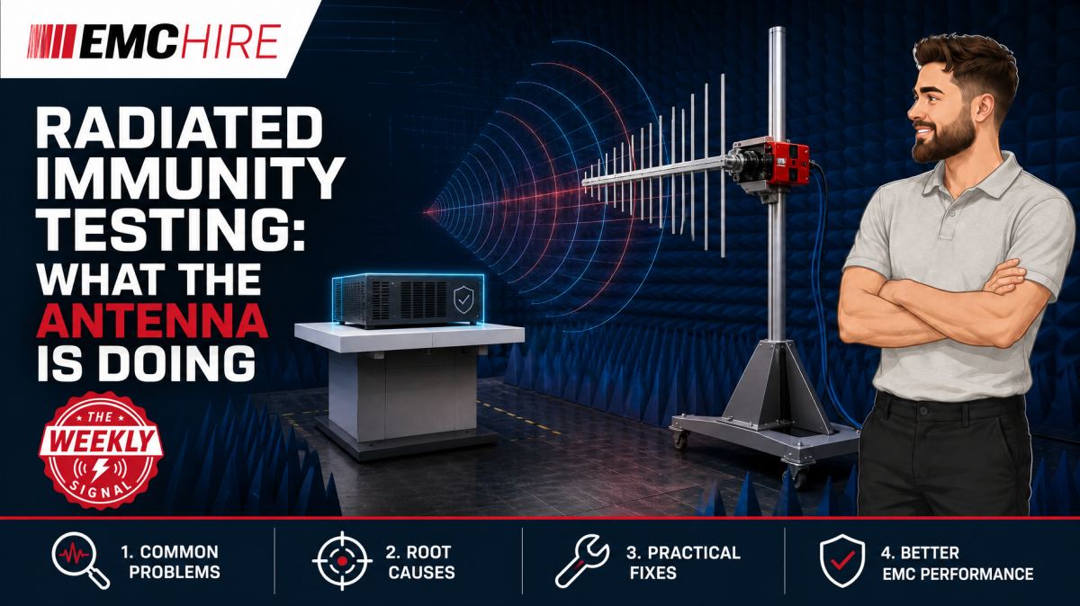
An immunity antenna is not simply transmitting RF towards the equipment under test. It is part of a calibrated system attempting to create a specified electric field across a defined test area, despite cable losses, reflections, antenna mismatch and frequency-dependent chamber behaviour.
What radiated immunity testing is trying to reproduce
Radiated immunity testing assesses whether equipment continues to operate acceptably when exposed to an RF electromagnetic field. IEC 61000-4-3 is the widely referenced basic test method for radiated RF electromagnetic-field immunity, although the product or product-family standard determines whether that method applies, the required test level, frequency range, modulation, dwell time, performance criteria and equipment configuration.
The test is intended to represent exposure to radio transmitters and other RF sources in the equipment's electromagnetic environment. It does not attempt to recreate every real transmitter. Instead, the laboratory establishes a controlled electric-field strength, usually expressed in V/m, and sweeps that exposure across the required frequencies while the equipment under test, or EUT, is operated and monitored.
That distinction matters. The pass or fail condition is not based on antenna input power. It is based on EUT performance while subjected to the specified field under the defined test conditions. Forward power is a means of producing the field, not the immunity test level itself.
What the antenna is actually doing
The signal generator produces the RF test signal. An RF power amplifier raises it to a usable level, directional coupling and power monitoring provide information about the drive system, and the antenna converts RF power at its terminals into an electromagnetic field.
No antenna performs that conversion uniformly across an unlimited bandwidth. Gain, impedance, radiation pattern, polarisation and power handling all change with frequency. Cable loss also rises with frequency, while amplifier output and mismatch tolerance vary across the operating band. The resulting field at the EUT therefore cannot be inferred safely from a single nominal antenna gain figure.
At each test frequency, the field arriving at the calibration plane is influenced by:
- net RF power reaching the antenna after cable and switching losses;
- antenna gain, radiation pattern and impedance match;
- distance and alignment between the antenna and calibration plane;
- reflections from the floor, walls, absorber, table, cabling and support equipment;
- the antenna's height, polarisation and proximity to conductive structures;
- amplifier compression, harmonics and protection behaviour.
Antenna selection must therefore address the whole test band and the required field strength. Broadband log-periodic, hybrid and horn antennas may be used over different ranges, depending on the facility and method. EMC Hire can help teams select suitable HF and VHF antennas or broader antennas and near-field probes for development work, but the frequency coverage printed on a datasheet is only the starting point. Required field, test distance, available amplifier power and chamber characteristics must also be checked.
Field strength is not the same as amplifier power
Engineers sometimes approach radiated immunity testing by asking how many watts are required. There is no reliable universal answer. In an idealised far-field calculation, electric-field strength is related to transmitted power, antenna gain and distance. A real immunity facility adds mismatch, cable attenuation, reflections, field non-uniformity and antenna pattern effects. The test arrangement must be calibrated rather than designed solely from the free-space equation.
Doubling amplifier power does not double field strength. Under ideal linear conditions, field strength varies with the square root of power, so doubling the electric field would require four times the RF power. In practice, the required increase may be greater at difficult frequencies because the antenna is inefficient, the chamber has a cancellation region or the amplifier is approaching compression.
Compression is particularly deceptive. The control software may request more drive, yet the amplifier output no longer rises proportionally. Harmonic energy can also increase. Unless forward power, amplifier operating margin and system behaviour have been characterised, the apparent power reserve may not exist when the field is applied to the EUT.
Field calibration and the uniform field area
Before testing the product, the laboratory establishes the relationship between frequency, applied RF power and electric-field strength over the defined calibration area. A calibrated isotropic field probe is positioned at prescribed points in the plane that the EUT will occupy. The method seeks to demonstrate acceptable field uniformity across the usable area, following the applicable edition and setup requirements.
The probe is not normally left in place as the primary field control during the EUT exposure. Calibration data are used to determine the forward power required at each frequency. This avoids the EUT itself distorting the field-probe reading and causing a feedback loop that drives the amplifier unpredictably.
Substitution has limits. Moving the antenna, changing its height, rerouting the RF cable or adding a conductive bench can alter the field distribution. A calibration from a superficially similar layout is not automatically transferable. Even a small antenna displacement can move a reflection maximum or minimum across the EUT face, particularly at higher frequencies.
Equipment used for field calibration and RF monitoring should have suitable calibration and frequency coverage. EMC Hire uses test equipment with calibration traceable through an appropriate ISO/IEC 17025 accredited calibration provider. Such traceability supports repeatability, confidence in recorded data and comparison between development measurements and later formal testing. It does not make the physical instrument or EMC Hire's facility itself ISO/IEC 17025 accredited.
Polarisation, orientation and cable coupling
Radiated RF does not couple only through the enclosure. Product cables often behave as receiving structures, developing common-mode currents that reach interface circuitry, power converters or internal references. A metal enclosure can perform well while a poorly bonded I/O shield provides a direct RF path into the PCB.
Testing commonly includes horizontal and vertical antenna polarisation where required by the applicable method. The EUT may also need exposure from multiple sides. Changing polarisation alters coupling to apertures, seams, PCB traces and cables. Rotating the product changes both the exposed face and cable geometry, so cable placement must be controlled rather than tidied differently for every orientation.
Near-field probes can help locate susceptible circuitry during debugging, but they do not reproduce a calibrated radiated immunity field. They are diagnostic tools. Likewise, conducted RF immunity testing using a CDN or another specified coupling method examines a different coupling path and must not be treated as a substitute for radiated exposure.
Operating modes and performance monitoring
A technically correct field is of limited value if the EUT is sitting in an idle state that does not exercise its susceptible functions. Motors should be loaded where appropriate, communications should carry representative traffic, sensor channels should be monitored at meaningful operating points and software should expose resets, corruption and timing disturbances.
Monitoring equipment can create its own immunity problem. Long oscilloscope leads, Ethernet cables or unfiltered camera supplies may carry RF into the EUT or fail independently. Fibre-optic links, filtered penetrations and electrically isolated monitoring are often preferable. The monitoring method should distinguish a real EUT degradation from a disturbed measurement instrument.
Acceptance also depends on the performance criteria called up by the applicable product standard. A brief deviation, self-recovery or operator intervention may be treated differently depending on the product and criterion. Teams should agree observable functions and pass or fail thresholds before starting the sweep. Deciding afterwards creates an evidence trail that is difficult to defend.
Typical scenario
Consider an illustrative industrial controller with a metal enclosure, external sensor leads, Ethernet and a switched-mode power supply. Early bench work shows no obvious problem, but the product team has not yet exposed the complete assembly to a controlled RF field.
The likely pre-compliance setup uses a signal generator, power amplifier, directional coupler, suitable broadband antenna and characterised test space. The controller runs representative communications and sensor activity while diagnostic data are observed through a fibre-isolated link. Antenna polarisation, EUT orientation and cable arrangement are recorded.
The team must decide which product standard applies, what frequency range and test level it requires, which ports and modes need monitoring, and whether the available amplifier and antenna can generate the required field with adequate margin. Selecting an antenna by frequency range alone may leave a power deficit in a low-gain region. Using an amplifier close to compression can produce an unstable or harmonically contaminated exposure.
Early investigation may reveal that RF current is entering through a cable shield termination or coupling into a high-impedance reset line. Correcting that before formal testing is usually less disruptive than changing the enclosure, PCB or production cable assembly after a failed programme.
EMC Hire can support equipment selection, pre-compliance engineering, on-site testing, facility access and formal compliance testing where appropriate. Hiring the antenna, amplifier and monitoring equipment for a defined development window can avoid capital expenditure and leave servicing, storage and calibration overheads outside the project. Formal results may then contribute to the technical file, EMC risk assessment, Declaration of Conformity and self-certification evidence where the applicable route permits. The manufacturer remains responsible for confirming the legislation, standards and conformity assessment requirements.
When to Hire EMC Equipment
A radiated immunity system is expensive to own properly. The antenna is only one component. Amplifiers, generators, couplers, RF cables, field probes, monitoring equipment and a suitable test environment all have frequency, power, calibration and maintenance constraints.
Hiring is technically sensible when testing demand is irregular, when a project needs a different frequency band from existing equipment, or when an amplifier is required only for a short investigation. It also allows a team to scale its capability during overlapping programmes without purchasing hardware that may be unsuitable for the next product family.
Ownership risk is often underestimated. High-power amplifiers require appropriate storage, cooling, maintenance and cautious operation into changing loads. RF cables can suffer internal damage without obvious external signs. Antennas are vulnerable to handling damage, while field probes and power sensors require controlled calibration arrangements.
For teams without a suitable test area, hiring instruments alone will not solve reflections, field uniformity or ambient control. Booking an EMC test facility or arranging on-site engineering support may provide a more defensible route. Accessible pre-compliance testing allows faults to be investigated before a formal programme, while calibrated engineering data improves correlation. It does not, by itself, prove compliance.
Common EMC Testing Mistakes to Avoid
Treating forward power as the test level
Recording amplifier watts without a valid field calibration does not demonstrate the electric field at the EUT. The same forward power can produce materially different field strengths after an antenna, cable or geometry change.
Moving the antenna after calibration
Changing antenna height, distance or alignment can invalidate the established field distribution. The error may appear only over a narrow frequency region, making it difficult to detect from forward-power records alone.
Allowing cable layouts to change between orientations
Cables can dominate RF pickup. If their height, bundling or route changes, a repeat test may exercise a different coupling path and produce either a false improvement or an unexplained failure.
Running the amplifier into compression
An amplifier at its limit may not deliver the expected field increase and may generate higher harmonic content. That weakens confidence in both the exposure level and the diagnosis of the susceptible frequency.
Testing an unrepresentative operating mode
An idle processor, inactive analogue channel or unloaded converter may conceal susceptibility that appears only during real operation. Every safety-related or functionally significant mode should be considered in the test plan.
Leaving incomplete records
Without photographs, antenna position, polarisation, cable layout, software version, dwell conditions and observed performance, the test may be impossible to reproduce. Weak records also reduce the value of the evidence in the technical file or during customer review.
Frequently Asked Questions (FAQs)
Can antenna gain be used to calculate the required amplifier size?
It can support an initial power budget, but it should not replace field calibration. Include cable loss, mismatch, antenna efficiency, test distance, chamber behaviour, modulation headroom and amplifier linearity. Margin is needed at frequencies where the system is least efficient.
Why is the field calibrated without the EUT?
The objective is to characterise the test facility and establish the power needed to generate the specified field over the calibration plane. Introducing the EUT during closed-loop probe control could distort the local field and cause misleading power corrections.
Does a higher field strength always provide better evidence?
No. Over-testing can trigger unrealistic failure mechanisms, exceed product safety constraints or stress protection components unnecessarily. The field level should follow the applicable product requirement or an agreed engineering investigation plan.
Can radiated emissions equipment be used for immunity testing?
Some antennas may have suitable bidirectional characteristics and power ratings, but a complete radiated emissions measurement system is not automatically an immunity system. Immunity testing requires an RF source, suitable power amplifier, power monitoring, field calibration and safe control of significant transmitted power.
Is IEC 61000-4-3 enough to define the product test?
Usually not by itself. It is a basic immunity test method. The relevant product or product-family standard may specify applicability, levels, ranges, operating modes, performance criteria and configurations. Verify the latest active editions, contractual requirements and market-specific obligations before fixing the test plan.
When is formal testing preferable to pre-compliance work?
Formal testing is appropriate once the design, configuration and test plan are sufficiently stable to generate controlled compliance evidence. Defence, automotive and aerospace programmes may require an appropriately accredited laboratory depending on contractual or programme rules. Pre-compliance work remains useful for finding weaknesses before that stage.
Planning a defensible radiated immunity test
If you need to size an amplifier, select an antenna, investigate an RF susceptibility or decide between equipment hire, on-site testing and a facility booking, discuss the setup with the EMC Hire engineering team. Support is available for pre-compliance work, practical debugging and formal compliance testing where appropriate.
Call +44 (0)1462 817111 or email sales@emchire.co.uk to request an equipment hire quotation, arrange on-site testing, discuss a formal test programme or book space at the EMC Hire test facility.
Disclaimer: Content is for informational purposes only and does not constitute formal engineering or regulatory advice. Always verify testing procedures against current official standards (e.g., ISO, MIL-STD, DEF STAN). EMC Hire Limited accepts no liability for outcomes resulting from the use of this information.