

What to record during a radiated emissions sweep
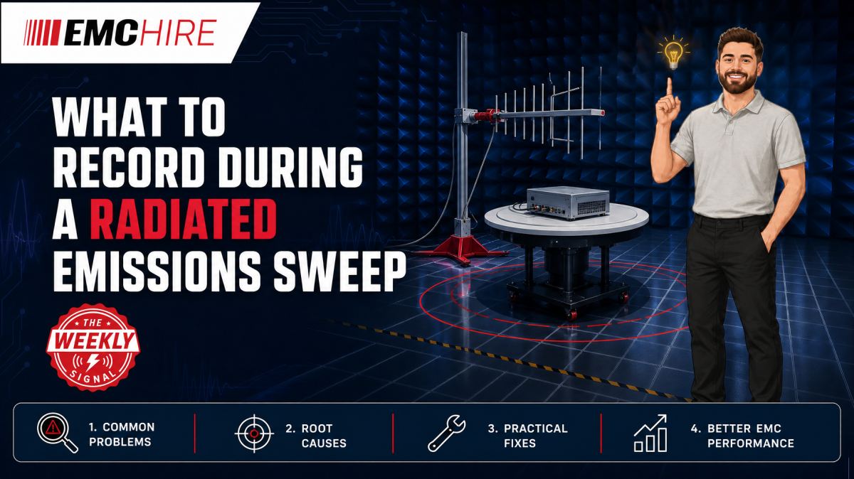
A radiated emissions plot without antenna position, detector settings and EUT configuration is only a picture. When a peak later becomes contentious, the missing metadata may make the measurement impossible to reproduce.
Why sweep metadata determines whether a result is useful
A radiated emissions sweep is normally used to identify disturbance frequencies, compare configurations and select signals for final measurement. The trace itself records amplitude against frequency, but it does not fully describe how the energy coupled from the equipment under test, or EUT, into the receiving antenna.
That distinction matters. A change in antenna height, turntable angle, cable position, operating mode or detector can move a peak by several decibels without any electrical modification to the product. If those conditions are absent from the record, engineers cannot distinguish a genuine design improvement from a change in measurement geometry.
Formal procedures depend on the applicable product or product-family standard. Radiated emissions commonly start at 30 MHz, but neither the upper frequency nor the required measurement method should be assumed. They may depend on the product scope, highest internal frequency, intended radio functions and applicable regulatory route. The latest active edition of the relevant standard, including its limits, detector requirements, measurement distance and prescribed configurations, must be checked before testing.
What to record during a radiated emissions sweep
Instrument identity and receiver configuration
Record the measuring receiver or spectrum analyser manufacturer, model, serial number, firmware where relevant and calibration status. EMC Hire uses test equipment with calibration traceable through an appropriate ISO/IEC 17025 accredited calibration provider. The accreditation applies to the calibration provider or calibration activity, not to the physical instrument.
Traceable and suitable calibration supports repeatability, confidence in recorded data and comparison between development and formal testing. It does not compensate for an incorrect test setup.
The receiver record should also contain:
- Start and stop frequencies.
- Frequency step, point count or sweep mode.
- Resolution bandwidth and video bandwidth, where independently configurable.
- Detector type, such as peak, quasi-peak or average.
- Sweep time or dwell time.
- Input attenuation, preamplifier state and any preselection setting.
- Trace mode, including clear-write, maximum hold or averaging.
- Any overload, compression or autoranging indications.
Do not treat these as administrative details. A fast swept peak detector can locate candidate frequency peaks efficiently, while quasi-peak and average detectors characterise signals differently. Substituting one detector for another may change the reported amplitude and can invalidate comparison against a detector-specific limit.
Likewise, the resolution bandwidth must match the applicable measurement requirements and frequency range. A narrower bandwidth may reduce indicated broadband noise but increase sweep time. A wider bandwidth can combine energy that the specified bandwidth would resolve separately. Record the actual setting rather than relying on a software preset name.
Antenna, cable path and correction data
Identify the antenna type, model, serial number and applicable calibration data. Record its polarisation, antenna height, measurement distance and physical orientation. For exploratory work using near-field probes or alternative antennas, state clearly that the result is diagnostic rather than a standards-compliant far-field measurement.
The selected antenna must cover the measured frequency range with suitable characterised data. EMC Hire provides access to HF and VHF antennas and a broader range of antennas and near-field probes for measurement and fault-finding work.
Record the RF cable identity or cable set, approximate routing and loss correction file. Include preamplifier gain, attenuator values and antenna factors used by the software. A plausible-looking corrected trace can still be wrong if it uses the calibration file for another antenna or an outdated cable-loss table.
Where antenna height is scanned, preserve either the height associated with each selected peak or the scan data needed to recover it. Writing only “height scan performed” is inadequate. The maximum at 120 MHz may occur at a different height from the maximum at 400 MHz because the site geometry, direct path and reflected path change with wavelength.
Turntable angle and physical geometry
Record the turntable angle associated with each investigated frequency. If the sweep uses continuous turntable rotation, document its direction, speed, angular range and the method used to retain maxima. For stepped measurements, retain the angular increment and dwell time.
Photographs are useful, but they need reference points. State what represents 0 degrees and whether the angle is reported from the EUT front face, turntable datum or another fixed axis. Without that convention, a later instruction to repeat a measurement at 210 degrees is ambiguous.
Also capture the EUT location on the table, table height, antenna separation and chamber or open-area test site identity. Even a modest displacement can alter coupling from a cable that is acting as the dominant radiator.
EUT operating mode and software state
The highest emission is not always produced by the mode drawing the most power. A low-load state may enable burst operation, clock gating or an intermittent communications process that generates a stronger narrowband component.
Record product model, serial number, hardware revision, firmware version and software build. Describe the exercised functions in engineering terms rather than writing “normal operation”. Useful records include processor load, display activity, radio state, motor speed, converter operating point, data traffic and peripheral activity.
If software cycles through modes automatically, log the cycle duration and synchronisation method. A receiver may otherwise miss an intermittent peak or capture it only on some sweeps, creating an apparent repeatability problem.
Cables, accessories and support equipment
List every connected cable, its type, length, termination and route. Record whether unused ports were open, terminated or populated. Photographs should show cable drops, bundled sections, support spacing and proximity to the ground plane.
Cable routing is part of the electromagnetic configuration. Moving an I/O cable away from the ground plane can change its common-mode impedance and effective radiating structure. A result obtained after casually rearranging cables may no longer represent the documented test configuration.
Identify auxiliary equipment, loads, simulators, fibre converters and power supplies. State whether support equipment was inside or outside the controlled test area and how its own emissions were assessed. Otherwise, a frequency peak from a laptop charger or interface converter may be incorrectly attributed to the EUT.
Peak records and ambient information
For each selected peak, retain frequency, corrected amplitude, limit, margin, detector, antenna polarisation, antenna height and turntable angle. Note whether the value came from an exploratory scan or a final maximised measurement. The distinction prevents a quick peak sweep from being mistaken for the formal result.
Store raw traces as well as exported plots where the instrument allows it. A bitmap cannot normally be reprocessed with corrected transducer factors or inspected at full frequency resolution.
Ambient signals should be identified where practical. Record the method used, such as switching the EUT off, removing its power or comparing antenna orientations. Do not simply delete known broadcast or mobile signals from the plot. Retaining the evidence shows why a signal was classified as ambient and helps explain gaps or elevated noise floors.
Typical scenario
Consider an illustrative laboratory sweep of a networked industrial controller. A vertical-polarisation peak appears close to the applicable limit during maximum hold, but the saved plot contains no turntable angle, antenna height or firmware build.
The team repeats the test after a filter change and observes a lower level. That looks encouraging, but the second run used a different cable route and the antenna remained at a fixed height. The apparent improvement cannot be attributed confidently to the filter.
A stronger approach is to establish a controlled test plan before the first sweep. The laboratory records the receiver settings, correction files, EUT modes and complete geometry, then maximises relevant frequency peaks using the method required by the applicable standard. Early testing in an accessible setup allows cables, shielding, bonding and filtering to be changed without consuming a formal test booking.
EMC Hire can support this work through equipment selection, radiated emissions measurement systems, facility access, pre-compliance engineering, on-site testing and formal compliance testing where appropriate. Hiring can cover a defined investigation window without committing capital to antennas, receivers and accessories that may not suit the next programme.
Turning sweep records into defensible evidence
A pre-compliance radiated emissions sweep does not automatically prove compliance. It can, though, provide calibrated engineering data, expose risk before formal testing and show why a mitigation decision was made.
For self-certification routes such as applicable CE or UKCA conformity processes, robust records may support the technical file, EMC risk assessment, Declaration of Conformity process and mitigation evidence. The manufacturer or responsible economic operator remains responsible for identifying the legislation, standards, conformity assessment route and documentation that apply.
Formal compliance testing provides a more controlled evidence trail for stakeholders and market-entry decisions, provided the test method and product configuration are appropriate. Defence, automotive and aerospace programmes may impose contractual methods or require final testing by an appropriately accredited laboratory. EMC Hire can provide pre-compliance support in these sectors, while the programme authority should confirm the status required for final evidence.
The United Kingdom Accreditation Service explains the role of accreditation in demonstrating competence. IEC basic immunity methods should not be confused with radiated emissions limit standards. Product and product-family standards define the relevant emissions requirements, configurations and limits for many products.
When to Hire EMC Equipment
Hiring is often appropriate when radiated emissions testing is concentrated around prototype builds, design reviews or a short compliance programme. Buying a receiver, antennas, preamplifiers, cables and positioning hardware for occasional use ties up capital and introduces continuing calibration, servicing, storage and asset-management costs.
Rental also lets the engineering team select equipment for the actual frequency range and test method. That reduces the risk of purchasing an antenna with unsuitable coverage, a receiver without the required detector functions or a system that cannot support future programmes.
During project peaks, hired equipment can expand internal capability without delaying another development team. It may also support correlation work before a formal facility booking. Where mains-port disturbance voltage is being investigated separately, a purpose-configured conducted emissions system and suitable LISN are required. A LISN is not part of the radiated measurement path and should not be treated as interchangeable with an antenna system.
Common EMC Testing Mistakes to Avoid
Saving the plot but not the raw data
An image records presentation, not necessarily the underlying measurement points or correction factors. If a transducer file is later found to be wrong, the sweep may need to be repeated.
Using peak data as a final detector result
Peak detection is useful for screening, but the applicable limit may require quasi-peak or average measurement. Reporting the screening value without detector context can create either a false failure or false confidence.
Recording one antenna height and angle for the whole sweep
Different frequencies maximise at different positions. A single geometry entry cannot describe a multi-frequency maximisation process and leaves the selected peaks difficult to reproduce.
Allowing cable positions to drift
Cables often form the dominant common-mode radiator. Unrecorded movement between sweeps can mask a design change or produce an apparent regression unrelated to the electronics.
Testing an unrepresentative operating mode
An idle unit may suppress clocks, interfaces or power-converter activity. Passing that configuration says little about the mode that customers will use and weakens the resulting evidence trail.
Ignoring receiver overload
A preamplifier can improve sensitivity, but strong ambient or EUT signals may drive it or the receiver into compression. The resulting trace can under-report emissions, generate intermodulation products or both.
Frequently Asked Questions (FAQs)
Should every frequency peak be fully maximised?
Not necessarily. Screening may identify many low-margin or clearly insignificant signals. The applicable standard, laboratory procedure and engineering risk should determine which peaks require formal maximisation and final detector measurement.
Is a screenshot sufficient for a pre-compliance sweep?
It is better than no record, but raw trace data, instrument state files, correction tables and setup photographs provide much stronger diagnostic value. Screenshots often omit overload status, trace mode and configuration details.
How should antenna height be recorded during an automated scan?
Retain the height linked to each selected frequency and, where possible, the underlying position-dependent data. Also record the scan range, speed or step size, polarisation and software method used to find the maximum.
Can near-field probe results be included in the same report?
Yes, provided they are labelled as diagnostic measurements. Near-field probes help locate sources and coupling paths, but their readings should not be presented as equivalent to a calibrated far-field radiated emissions result.
How much setup photography is enough?
Use enough views to reconstruct the geometry: overall chamber layout, each EUT face, cable routing, support equipment, antenna polarisation and turntable datum. Add written dimensions where perspective could be misleading.
Does calibrated equipment make a sweep compliant?
No. Calibration supports measurement accuracy and traceability, but compliance evidence also depends on the applicable standard, suitable test site, correct method, valid configuration, competent execution and complete records.
Discuss the test setup before committing the test window
If you need to define a radiated emissions sweep, reproduce an uncertain result or prepare for formal testing, speak with the EMC Hire engineering team. Support is available for equipment hire, pre-compliance investigation, formal compliance testing where appropriate, on-site testing and bookings at the EMC Hire test facility.
Call +44 (0)1462 817111 or email sales@emchire.co.uk to discuss the frequency range, applicable product standard, EUT configuration and evidence you need to retain.
Disclaimer: Content is for informational purposes only and does not constitute formal engineering or regulatory advice. Always verify testing procedures against current official standards (e.g., ISO, MIL-STD, DEF STAN). EMC Hire Limited accepts no liability for outcomes resulting from the use of this information.