

Shielding effectiveness testing for equipment enclosures
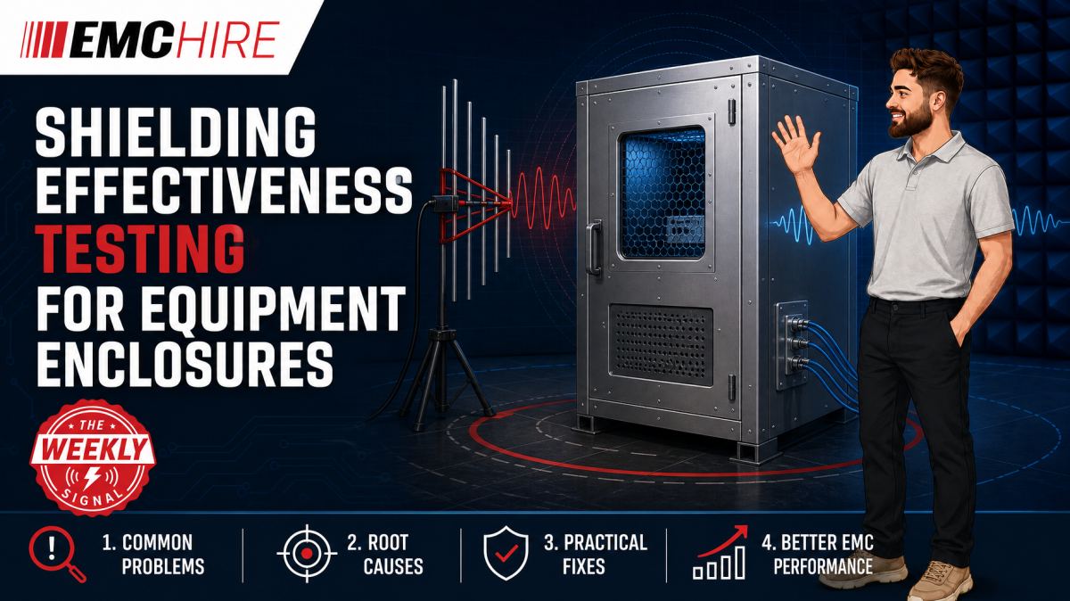
A cabinet can look electrically continuous and still leak badly through a display aperture, door seam or filtered cable entry. Shielding effectiveness testing finds the complete enclosure weakness, not merely the quality of its metalwork.
What shielding effectiveness testing measures
Shielding effectiveness testing quantifies how much an enclosure reduces electromagnetic energy passing between its interior and exterior. The enclosure may be an equipment cabinet, screened room, modular shelter, medical system housing or rail control enclosure.
The result is normally expressed in decibels as the ratio between a reference field or received signal and the corresponding value with the shielding barrier in place. For an electric-field measurement, the basic relationship is:
SE = 20 log10(Ereference / Eshielded) dB
Equivalent ratios can be formed for magnetic-field strength or received voltage where the measurement arrangement supports them. This apparently simple calculation hides most of the measurement difficulty. Transmit power, antenna position, polarisation, cable coupling, receiver linearity, ambient signals and chamber reflections must remain adequately controlled between the reference and shielded measurements.
Shielding effectiveness is not one fixed property across frequency. Low-frequency magnetic performance depends heavily on material permeability, thickness and enclosure geometry. At higher frequencies, seams, apertures, conductive gaskets, ventilation panels and penetrations often dominate. A cabinet reporting strong attenuation at one frequency can perform poorly a few octaves away.
Where enclosure testing fits into EMC validation
Shield testing is a diagnostic and verification activity. It does not replace product-level emissions or immunity testing.
Radiated emissions testing measures disturbances produced by operating equipment against the applicable limit. Radiated immunity testing exposes the equipment to a defined field and assesses its performance. Shielding effectiveness testing instead characterises the attenuation provided by the enclosure or screened volume under a specified arrangement.
The distinction matters. An enclosure with modest measured attenuation may still support a compliant product if the internal source is weak and the circuitry is tolerant. Conversely, a cabinet showing high attenuation in an empty-shell test can fail to control emissions once unfiltered cables, displays and cooling assemblies are installed.
For defence programmes, shielding results may support enclosure development before testing against contractual requirements such as those calling up MIL-STD-461 test methods or relevant defence standards. Rail and medical teams should identify the applicable product or product-family requirements rather than assuming a generic EMC standard defines enclosure attenuation. Medical equipment developers can review EMC within the wider context of medical device testing, while generic immunity standards may provide useful background but do not automatically apply to every product. EMC Hire's guide to EN 61000-6-1 and EN 61000-6-2 generic immunity requirements explains that distinction.
Selecting a standards-based test method
IEEE 299
IEEE 299 is widely referenced for measuring the effectiveness of electromagnetic shielding enclosures. It covers measurement principles for magnetic, electric and plane-wave regions, with test arrangements selected according to frequency, enclosure size and intended performance.
The engineer must review the current published edition and its scope before writing a test plan. Enclosure dimensions matter because source distance, antenna separation and available internal space determine whether the prescribed geometry can be achieved. A method intended for a large screened room may not transfer cleanly to a compact electronics cabinet.
Related IEEE documents may address smaller enclosures or different geometrical conditions. The document named in a contract should not be replaced merely because another method is easier to perform. Any proposed deviation needs technical justification and agreement from the responsible parties.
EN 50147-1
EN 50147-1 has historically been used for measuring the shielding attenuation of EMC test sites and anechoic chambers. It may still appear in procurement specifications, facility records and older validation plans. Its relevance to a finished equipment cabinet should be checked carefully because a chamber verification method and a cabinet acceptance test do not necessarily answer the same engineering question.
Standards status also changes. Teams should confirm whether EN 50147-1 remains the applicable contractual reference, whether it has been superseded for the intended application, and which current European or international method should be used. Checking the title alone is insufficient.
MIL-STD-285
MIL-STD-285 is a legacy shielding effectiveness method that remains visible in older defence specifications and supplier drawings. It should not automatically be selected for a new programme. Where a contract still cites it, the project authority needs to establish whether the original method, a later replacement or a tailored procedure governs acceptance.
Legacy terminology can conceal significant differences in antenna type, spacing, frequency coverage and acceptance criteria. The UK Ministry of Defence provides access to defence standards information through the UK Defence Standardization service, but programme-specific contractual requirements still need review. EMC Hire also supports development teams working within the broader defence EMC testing environment.
Building a defensible measurement plan
A useful test plan begins with the enclosure's purpose. Is the requirement intended to protect sensitive receivers, contain high-power RF, reduce emissions from digital electronics or demonstrate the integrity of a screened room? The answer determines the relevant frequency range, test points, polarisations and required dynamic range.
Test points should target likely leakage paths rather than follow an arbitrary grid alone. Typical locations include:
- doors, hinges, latches and removable panels;
- conductive gasket joints and corner interfaces;
- ventilation honeycombs and fan assemblies;
- displays, windows and optical apertures;
- power, signal, RF and fibre penetrations;
- bonding straps, earth studs and mechanically joined sections.
The baseline arrangement must be defined before testing. Depending on the method, this may involve a free-space or open-aperture reference measurement, followed by a measurement through the completed shield. Moving an antenna by a small fraction of a wavelength at higher frequencies can change the received signal through standing-wave effects. That movement can be mistaken for shielding performance unless geometry is controlled.
Dynamic range needs equal attention. If the shielded signal falls into the receiver noise floor, the result is only a lower bound on attenuation. Reporting the calculated number without a noise-floor qualification overstates the evidence. Preamplifiers can improve sensitivity, but the complete receive chain must remain linear in the presence of strong ambient or transmitted signals.
Apertures, seams and penetrations
An aperture behaves differently according to its dimensions, shape, frequency and field orientation. Long narrow slots are often troublesome when the electric field is aligned across the slot. Door seams can therefore produce strongly polarisation-dependent results.
Penetrations usually decide real cabinet performance. A filtered mains inlet bonded through painted metal may provide far less attenuation than its component data suggests. The paint layer adds contact impedance, while long bonding conductors add inductance. At higher frequencies, the filter case and cabinet wall must behave as one RF boundary.
Cables can also bypass the shield. Test leads routed through a door or connected without representative filters create an unintended coupling path. The resulting figure then characterises the temporary cable arrangement rather than the production enclosure.
Typical scenario
Consider an illustrative rail or defence electronics cabinet containing switched-mode power conversion, digital processing and sensitive analogue acquisition. The mechanical team has selected conductive door gaskets and filtered ventilation panels, but the cable-entry plate is still under development.
An early shielding effectiveness test can compare plate layouts before the production design is frozen. The likely setup uses a signal generator and suitable power amplification on the transmit side, antennas or magnetic-field transducers appropriate to the selected frequency region, and a calibrated receiver or spectrum analyser on the receive side. The exact arrangement must follow the chosen method rather than a convenient improvised geometry.
The team must decide whether to test an empty enclosure, a representative populated cabinet or both. Empty-shell testing isolates mechanical shielding performance. Testing with production penetrations and cables gives a more realistic system result, although active electronics may generate signals that complicate measurement.
Selecting antennas with inadequate bandwidth, insufficient receiver dynamic range or unsuitable near-field behaviour can produce reassuring but meaningless attenuation figures. Early investigation exposes those limitations while gasket design, connector placement and bonding details can still be changed. Waiting until formal product EMC testing may turn a replaceable entry plate into a full cabinet redesign.
EMC Hire can support equipment selection, pre-compliance measurements, on-site testing and access to test facilities. Suitable equipment with calibration traceable through an appropriate ISO/IEC 17025 accredited calibration provider supports repeatability and comparison between development and later formal work. Pre-compliance data does not itself prove conformity, but it gives engineers a stronger basis for design decisions and test readiness.
When to Hire EMC Equipment
Shielding projects often need a wide frequency range for only a few days. Purchasing signal sources, amplifiers, antennas, probes and sensitive receivers for an irregular test programme ties up capital in equipment that must then be stored, serviced and kept within calibration.
Hiring is particularly practical when the required configuration changes between cabinets. A screened room survey may demand different transducers, power and dynamic range from a compact enclosure investigation. Rental allows the measurement chain to be matched to the defined test window rather than forcing an unsuitable owned instrument into the method.
It also helps during project peaks. Engineering teams can add temporary capability for factory acceptance work, site investigations or pre-compliance debugging without committing to equipment that may not suit the next programme. EMC Hire can help review bandwidth, connector interfaces, amplifier power, receiver sensitivity and calibration status before despatch, reducing the risk of discovering a system mismatch on the test day.
Common EMC Testing Mistakes to Avoid
Changing geometry between reference and shielded measurements
Uncontrolled antenna movement changes path loss and standing-wave conditions. The calculated difference may then include a geometry error that is indistinguishable from enclosure attenuation.
Ignoring the measurement noise floor
A receiver displaying its own noise does not demonstrate the enclosure's true attenuation. Results should identify the system floor and report lower-bound performance where the shielded signal cannot be resolved.
Testing an unrepresentative enclosure
Removing doors, cables, fans or connector panels for convenience can eliminate the dominant leakage mechanism. The measurement may be repeatable, yet irrelevant to the production assembly.
Using poor bonding at filters and panels
Long straps, painted interfaces and loose fasteners increase RF impedance. A filter tested as a component cannot deliver its expected installed performance if disturbance current flows around its case through a poor cabinet bond.
Recording too little setup information
A report without antenna locations, polarisation, test-point photographs, cable routes, equipment settings and enclosure configuration cannot be reproduced reliably. It also provides weak mitigation evidence for the technical file, customer review or later fault investigation.
Applying a familiar standard outside its scope
IEEE 299, EN 50147-1 and MIL-STD-285 are not interchangeable labels for any shielding test. Using the wrong method can create an acceptance result that does not meet the contract or represent the enclosure's operating environment.
Frequently Asked Questions (FAQs)
Can shielding effectiveness be predicted from material data?
Material properties support modelling, but complete-enclosure performance is commonly limited by seams, apertures, joints and penetrations. A high-conductivity panel does not compensate for a poorly bonded connector plate.
Should an enclosure be tested empty or populated?
Both may be useful. Empty-shell testing isolates mechanical construction, while representative population reveals bypass paths introduced by cables, filters and accessories. The test objective and standard should define which configuration forms the acceptance evidence.
Does a high shielding figure guarantee product EMC compliance?
No. Product compliance depends on applicable emissions limits, immunity requirements, operating modes, ports and performance criteria. Shielding effectiveness is one design input, not a substitute for product-level testing.
How many enclosure locations should be measured?
The selected standard or contractual plan may specify minimum positions. Additional measurements should cover suspected leakage paths. A single centre-panel reading is rarely sufficient for a cabinet containing doors, vents and cable entries.
Can pre-compliance shielding data support CE or UKCA documentation?
Calibrated engineering data may support risk assessment, mitigation records and the technical file, but it does not automatically establish conformity. The manufacturer or responsible economic operator must confirm the applicable legislation, standards, conformity assessment route and documentation requirements.
What must be checked before testing?
Confirm the latest active edition and scope of every referenced standard, along with frequency ranges, test levels, geometries, equipment configurations, acceptance limits and reporting requirements. Defence, rail and medical programmes may add customer-specific or contractual provisions, and final testing may require an appropriately accredited laboratory depending on the programme.
Planning the next measurement
A technically sound shielding survey starts with the requirement, not the available antenna. EMC Hire can help define a suitable equipment chain, arrange equipment hire, support on-site measurements, provide accessible pre-compliance engineering or discuss formal compliance testing where appropriate. Test facility space can also be booked for controlled development and validation work.
For advice on shielding effectiveness testing, call +44 (0)1462 817111 or email sales@emchire.co.uk. Sharing the enclosure dimensions, target frequency range, referenced standard and required attenuation will allow the engineering team to assess the test approach more accurately.
Disclaimer: Content is for informational purposes only and does not constitute formal engineering or regulatory advice. Always verify testing procedures against current official standards (e.g., ISO, MIL-STD, DEF STAN). EMC Hire Limited accepts no liability for outcomes resulting from the use of this information.