

Measuring emissions from a prototype enclosure
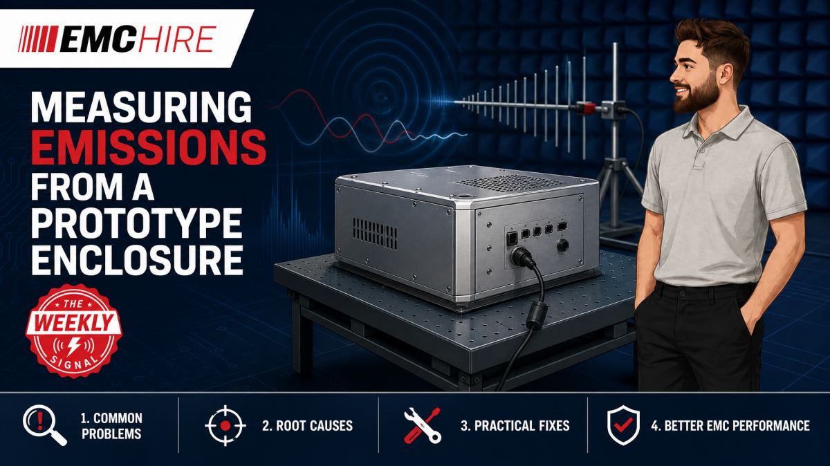
A prototype enclosure can appear electrically quiet until one seam, display opening or temporary cable exit turns an internal clock current into an efficient radiator.
Testing before final tooling is worthwhile, but only if the enclosure, fixture, cabling and antenna geometry are controlled well enough to separate genuine design behaviour from artefacts of the prototype setup.
What prototype enclosure emissions testing can tell you
Early enclosure measurements are rarely a complete substitute for formal compliance testing. They are a way to identify radiation mechanisms, compare mechanical options and reduce the chance that a tooling decision fixes an EMC weakness into the production design.
The aim should be stated before equipment is assembled. A comparison test may ask whether a conductive gasket reduces a narrowband emission. A diagnostic test may seek the aperture responsible for radiation at a processor harmonic. A pre-compliance exercise may estimate margin against the radiated emissions requirements called up by the applicable product or product-family standard.
Those are different jobs. Comparative work can be useful with a controlled, non-standardised distance, provided every relevant condition remains unchanged. Evidence intended to predict formal performance needs a setup much closer to the specified measurement arrangement, including antenna type, distance, EUT orientation, cable layout, detector, bandwidth and site conditions.
Product development teams should first establish which product standard applies. CISPR 11 and CISPR 32 are examples containing emissions requirements for particular equipment scopes, but neither applies universally. Product-specific requirements may alter the ports, operating modes, limits and frequency range under consideration. Check the latest active edition, national adoption, product scope and contractual test plan rather than carrying settings across from a previous project.
Why apertures and seams radiate
An enclosure does not suppress emissions simply because it is metal. Shielding depends on electrical continuity, geometry, material properties and the relationship between internal sources and enclosure discontinuities.
Slots, ventilation patterns, connector cut-outs and poorly bonded seams can support displacement or conduction currents. Radiation generally becomes more troublesome as the effective aperture dimension becomes significant relative to wavelength, although resonance, source position and coupling can make much smaller features relevant. A long narrow seam may behave differently from a circular hole with the same area. Treating shielding solely as a percentage of open area misses the current-path physics.
Contact spacing also matters. A removable panel held at four corners may have an acceptable direct-current resistance yet present substantial transfer impedance at RF. Paint, anodising, adhesive films and uneven gasket compression further alter the bond. Measuring milliohms at DC does not prove that a joint is effective at several hundred MHz.
Temporary prototype construction adds another complication. Conductive tape can be a useful diagnostic tool, but it may create an unrealistically continuous bond. Conversely, a loosely assembled rapid prototype can make a sound production concept look poor. Record screw spacing, torque where controlled, surface finish, gasket type, overlap and tape position. Otherwise the mechanical team cannot translate the result into a production requirement.
Build a representative fixture, not a convenient one
The fixture often determines whether the test answers a useful question. Metal support frames, unplanned ground straps and laboratory power supplies can modify common-mode current paths. A wooden table is not automatically transparent either, particularly if cables are draped against supports or routed differently between scans.
Replicate the intended installation where the relevant standard requires it or where normal use materially affects emissions. Rack-mounted equipment, wall-mounted controllers and products bonded to a vehicle structure can behave quite differently when tested free-standing. If the production enclosure relies on a chassis bond, represent its length, width and connection method. An unnecessarily long braid adds inductance and may leave the enclosure floating at higher frequencies, even though a continuity meter indicates a connection.
The fixture should allow repeatable rotation and cable placement without obscuring likely radiating faces. Mark cable exit points, bend positions and excess-length arrangements. Photograph the setup from several angles and include a scale or dimensioned sketch. A statement such as “cables arranged normally” is not enough to reproduce a marginal peak six weeks later.
Antenna placement and measurement discipline
For radiated emissions, use an antenna appropriate to the required frequency range and measurement method. EMC Hire provides access to suitable HF and VHF antennas and wider radiated emissions measurement systems. Equipment selection must account for antenna factor, receiver range, preamplifier headroom, cable loss and the applicable standardised geometry.
Radiated emissions measurements commonly start at 30 MHz, but that is not a universal lower limit. The upper frequency depends on the product, its highest internal frequencies and the applicable requirements. Detector and resolution bandwidth settings must also follow the relevant standard. Peak detection is useful for fast exploratory scans, while quasi-peak or average measurements may be required for comparison with particular limits. A peak scan should not be relabelled as a final quasi-peak result.
Maintain the specified measurement distance from the defined reference points, not from whichever surface is easiest to reach. On a large enclosure, a modest distance error changes field strength and geometry enough to damage comparison between builds. Antenna height and polarisation should be explored where the method requires it because enclosure currents can produce strongly polarised fields.
Ambient signals need active management. Run an ambient scan with the EUT off, then correlate suspect frequencies with EUT state changes, clock settings or functional modes. Ambient subtraction performed blindly can conceal a real emission or manufacture apparent margin. Time-domain observation, frequency stability and near-field localisation are often more informative than simple numerical subtraction.
Near-field probing without mistaking it for compliance data
Near-field probes are effective for locating leakage around apertures, seams, connectors and internal sources. Magnetic probes respond primarily to local magnetic fields and current loops, while electric-field probes are more sensitive to voltage-driven structures. Neither directly predicts a far-field limit without a validated correlation method.
Probe orientation, distance and hand position can change the reading substantially. Use a non-conductive guide or marked spacer, scan a defined grid and preserve the same receiver settings for comparisons. Touching a seam with the probe or allowing its cable to lie against the enclosure alters the field being investigated.
A useful sequence is to identify a far-field peak, confirm that it tracks EUT operation, then tune the receiver to that frequency and scan likely leakage paths. Temporarily bridging a seam with conductive tape can test the hypothesis. If the peak falls, repeat the modification and removal to rule out drift or an accidental cable movement.
Do not overlook conducted common-mode currents
Radiation from an enclosure is often driven by cables rather than directly through a panel. A cable leaving through a well-designed connector aperture can still act as an antenna if common-mode current is present. Clamp-on current probing can help diagnose this mechanism, although its readings are not interchangeable with radiated field strength.
Power-port conducted emissions should be assessed separately using a suitable LISN where required by the applicable method. A LISN presents a defined impedance and couples conducted disturbance voltage to a measuring receiver. It is not a conducted immunity device. EMC Hire can supply information on conducted emissions systems for complementary power-port investigations.
Correlating cable current, conducted disturbance voltage and radiated peaks often reveals more than examining any one plot alone. A filter change that improves LISN results may have little effect on radiation if the dominant path is a shield termination or signal cable.
Typical scenario
Consider an illustrative industrial controller built into a folded aluminium prototype enclosure. The production version will use formed seams and a gasketed display aperture, but the early unit has bolted corners, a machined display opening and temporary cable glands. The electronics contain a processor, switch-mode converters and external Ethernet and power connections.
The team first needs to decide whether it is comparing enclosure variants or estimating formal-test margin. For comparison work, it can hold the receiver, antenna placement, EUT orientation and cable fixture constant while changing one feature at a time. Suitable changes might include bonding the display bezel, reducing seam spacing or altering shield termination at a connector.
For a broader pre-compliance assessment, the EUT should exercise representative worst-case operating modes. Communications need realistic traffic, converters need representative load and displays should use modes likely to maximise activity. Testing an idle processor may produce a clean plot that has little relationship to normal operation.
A peak scan can identify frequencies and orientations for further investigation. Near-field probing then helps locate the associated seam or aperture, while a current probe can establish whether external cables are involved. Once modifications are stable, measurements using the required detector and test geometry provide a more defensible estimate of margin.
Hiring the receiver, antennas, probes and ancillary equipment allows the team to assemble the correct system for this defined window without buying instruments that may not suit the next programme. EMC Hire can also support equipment selection, test setup, accessible pre-compliance work, on-site testing or facility-based measurements. Formal compliance testing may then be planned against the applicable product requirements, without implying that earlier diagnostic measurements prove compliance.
When to Hire EMC Equipment
Prototype enclosure emissions work often occurs in short, intense periods around mechanical releases. Purchasing a complete measurement chain for an irregular requirement ties up capital and leaves the owner responsible for storage, servicing, software support and calibration.
Hiring is technically sensible when the required antenna range or receiver capability changes between projects, or when several teams need parallel setups during a development peak. It also reduces the risk of purchasing an instrument that later proves incompatible with a higher-frequency programme, a different detector requirement or a particular transducer.
The rental specification should cover the whole chain, including receiver or spectrum analyser, antenna, cables, preamplifier where appropriate, limit-line or control software, near-field probes and any conducted measurement accessories. Omitting a characterised RF cable or suitable adaptor can compromise amplitude accuracy and delay the work.
Where calibration affects recorded measurements, EMC Hire uses test equipment with calibration traceable through an appropriate ISO/IEC 17025 accredited calibration provider. Traceable and suitable calibration supports measurement confidence, repeatability and comparison between development and formal testing. It does not make a prototype setup compliant with a standard by itself, nor does accreditation attach to the physical instrument.
Common EMC Testing Mistakes to Avoid
Changing cable routing between enclosure variants
External cables can dominate radiation. Moving one cable while replacing a lid changes two variables, so any improvement cannot confidently be attributed to the enclosure. Use marked routes, controlled support points and repeatable excess-length arrangements.
Using a temporary bond that production cannot reproduce
Continuous copper tape may demonstrate that a seam is responsible, but it does not validate a production joint using sparse screws over painted metal. Translate the diagnostic result into measurable production details such as contact finish, fastener spacing and gasket compression.
Ignoring antenna placement
Small distance, height or polarisation changes can shift a measured peak. An undocumented bench scan may locate a problem, but it provides weak comparison data and an unsuitable evidence trail for later review.
Applying the wrong detector or bandwidth
Receiver settings copied from another frequency range or standard can change measured amplitudes and pulse weighting. Follow the applicable CISPR or product-standard method, and label exploratory peak data honestly.
Testing an unrepresentative operating mode
An idle interface, reduced processor load or disconnected accessory can suppress the emission mechanism. Define software version, traffic, loads, peripherals and duty cycles in the test record.
Failing to control ambient noise
Broadcast, mobile and local digital signals can be mistaken for EUT emissions. Record EUT-off scans and use operational switching to establish correlation rather than deleting inconvenient peaks without evidence.
Frequently Asked Questions (FAQs)
Can a bench test predict formal radiated emissions performance?
It can identify dominant frequencies and compare design changes, but prediction quality depends on site characteristics, geometry, equipment and correlation with the formal method. Treat bench results as engineering evidence, not automatic proof of compliance.
Should apertures be tested individually?
Where practical, yes. Change or cover one feature at a time while preserving cable and antenna positions. Multiple simultaneous modifications may improve the plot but leave the responsible mechanism unknown.
How close should a near-field probe be?
There is no universal diagnostic spacing. Choose a distance that provides useful spatial resolution without contacting or loading the structure, then keep it fixed for comparisons. Record probe type, orientation, spacing and receiver settings.
Does low seam resistance prove good shielding?
No. A DC measurement may reveal gross bonding faults, but RF performance depends on transfer impedance, inductance, contact distribution and seam geometry. A joint can measure well with a multimeter and still leak at high frequency.
What documentation should be retained?
Keep plots and raw data alongside photographs, dimensions, cable routes, operating modes, software versions, enclosure configuration, instrument identities, calibration status and receiver settings. This information strengthens the technical file and makes later measurements reproducible.
Can pre-compliance data support CE or UKCA self-certification?
Calibrated pre-compliance data may support engineering decisions, EMC risk assessment, mitigation evidence and technical documentation where the chosen conformity route allows it. The manufacturer or responsible economic operator remains responsible for confirming the legislation, standards, test levels, limits, documentation and conformity assessment route. Testing alone does not complete every obligation.
Plan the enclosure investigation before tooling
Mechanical and electronic teams should agree the questions before the prototype reaches the test area. Define the enclosure variants, expected operating modes, cable fixture and acceptance criteria. Early investigation leaves time to alter seam geometry, connector bonding and aperture treatment without cutting production tooling.
For help selecting equipment, arranging on-site testing, booking space at the EMC Hire test facility, or discussing pre-compliance and formal compliance testing, contact the EMC Hire engineering team on +44 (0)1462 817111 or email sales@emchire.co.uk. The discussion can cover the applicable test method, measurement chain and evidence required before committing to a hire or test programme.
Disclaimer: Content is for informational purposes only and does not constitute formal engineering or regulatory advice. Always verify testing procedures against current official standards (e.g., ISO, MIL-STD, DEF STAN). EMC Hire Limited accepts no liability for outcomes resulting from the use of this information.