

Why shielding can reduce one peak and create another
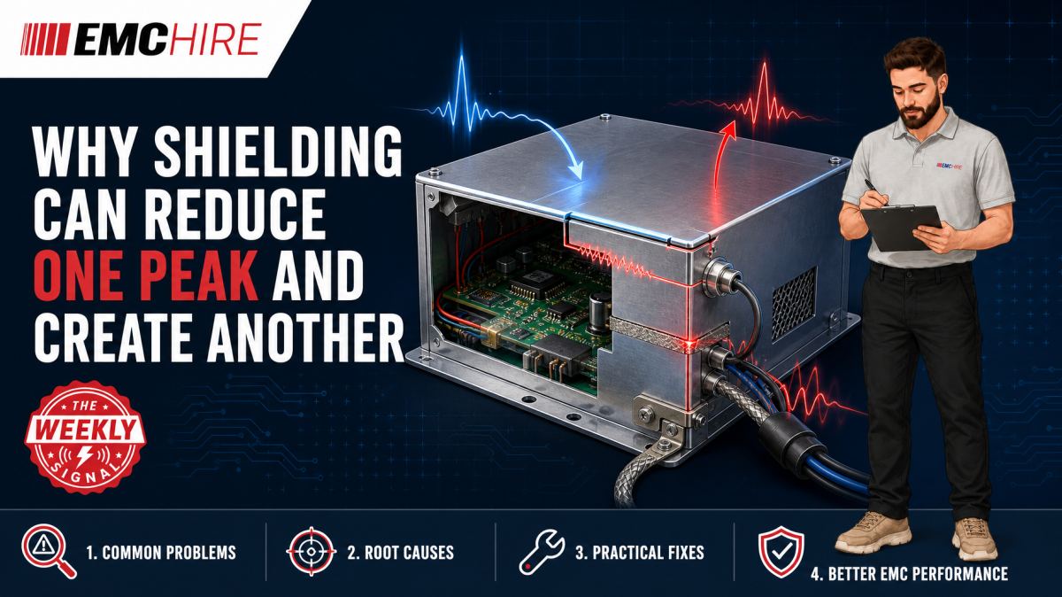
A shield does not remove electromagnetic energy. It changes where the energy flows, resonates and escapes, which is why suppressing one peak can expose or create another.
Why EMC shielding peaks move rather than disappear
Adding conductive foil, a screening can, a shielded cable or a metal enclosure often produces an immediate improvement at the frequency under investigation. The surprise comes when a nearby peak rises, a lower-frequency problem appears, or the dominant emission moves to another cable.
This is not necessarily a bad measurement. Shielding changes the impedance and geometry of the complete electromagnetic system. Current that previously coupled through an electric field may be redirected into a chassis joint, cable screen, connector shell or aperture edge. A structure that was electrically small can become resonant after its dimensions, capacitance or return path are altered.
The first question should therefore be broader than, “Did the shield attenuate the original source?” Ask what happened to the source current, its return path and every remaining route to the outside world.
Shielding effectiveness depends on the complete coupling path
Shielding effectiveness is commonly discussed in terms of reflection, absorption and multiple reflections within the material. Those mechanisms matter, but practical enclosures are rarely continuous sheets. They contain seams, ventilation, displays, connectors, paint, fasteners and cables. System performance is often controlled by these discontinuities rather than the bulk conductivity of the metal.
A useful troubleshooting model separates the problem into source, coupling path and victim. For emissions work, the “victim” may be the measurement antenna or conducted emissions receiver. If shielding weakens one coupling path but another remains available, the observed spectrum can change shape without the source itself becoming quieter.
For example, foil placed over a processor area may reduce direct electric-field coupling to an enclosure seam. If the foil is bonded to digital ground through a long pigtail, RF current can instead flow through the pigtail and common impedance into an I/O reference. The attached cable then becomes a more effective common-mode antenna. The local probe result improves while the chamber result worsens.
Our guide to shielding effectiveness measurement discusses the wider measurement problem. The main lesson is that material data alone cannot predict the performance of an assembled product.
Resonance can turn a shield into part of the radiator
A conductive cover introduces dimensions and boundaries that support resonant behaviour. Parallel panels can form cavity modes. A long seam may behave as a slot antenna. A shield connected at only one or two points may act as a plate with appreciable RF voltage relative to the chassis.
Resonance is not limited to an obvious half-wavelength structure in free space. Dielectrics, nearby conductors, cable loading and distributed capacitance alter electrical length. Narrow bonding features also add inductance. A connection that looks like a short circuit on a drawing may have enough RF impedance to permit substantial voltage across the joint.
Suppose an illustrative product has a switching converter harmonic producing a radiated peak. A screening cover reduces the local electric field around the converter. The cover also increases capacitance to a nearby chassis panel and is bonded through two corner fasteners. That arrangement can support a circulating current path around the cover perimeter. At another frequency, the current maximum may coincide with a seam or cable entry, raising a new radiated peak.
Do not diagnose this solely by comparing peak amplitudes. Track harmonic relationships, cable current and field distribution. A new peak that remains phase-related to the same clock or converter may be a redistributed coupling path, not a new noise source.
Apertures and seams determine where energy escapes
An aperture need not be large to cause trouble. Its longest dimension, orientation and position relative to internal current maxima all matter. Several small holes arranged as a long slot can perform worse than their total open area suggests. A display opening or ventilation seam located where enclosure surface current is high may dominate radiation.
Changing the shielding can also move the internal field maximum towards an existing aperture. The aperture has not physically changed, but its excitation has. This explains why applying conductive tape to one seam sometimes increases leakage from the opposite side of the enclosure.
Near-field scanning around seams is useful for locating leakage, but probe orientation must remain controlled. An electric-field probe and magnetic-field probe respond to different field components. Changing probe angle or spacing between measurements can create an apparent improvement that is larger than the shielding change itself.
Where enclosure performance must be assessed away from a conventional laboratory, on-site shielding effectiveness testing can help identify leakage through doors, penetrations, joints and installed services. Test geometry and environmental conditions must be recorded carefully because ambient signals and antenna placement can otherwise obscure comparatively small changes.
Bonding impedance matters more than DC continuity
A continuity buzzer proves very little at RF. A painted joint pierced by one fastener may show low DC resistance while presenting a high-inductance current path at higher frequencies. Long wires and pigtails are particularly troublesome because their impedance rises with frequency and their loop area encourages magnetic coupling.
Good RF bonding generally requires a short, wide and repeatable connection with controlled metal-to-metal contact. Conductive gaskets can help, but only when compression, surface finish, corrosion behaviour and mechanical tolerances are managed. Excess compression may damage a gasket; insufficient compression leaves local gaps that create leakage and variable contact impedance.
More bonding points are not automatically better. Additional connections can create circulating chassis currents or couple noisy references into previously quiet structures. The correct arrangement depends on frequency, safety requirements, cable architecture and whether the enclosure is intended as an RF reference, a protective earth structure, or both.
Cable screens can relocate the dominant peak
Once direct enclosure radiation is reduced, external cables often become the dominant path. Common-mode current can be driven onto a cable through connector capacitance, imperfect screen termination or shared return impedance. A cable screen terminated by a pigtail has poor high-frequency transfer impedance compared with a well-controlled circumferential termination.
Measure cable common-mode current before and after the shielding modification, using a suitable current probe and repeatable position. A reduction in local enclosure field accompanied by increased cable current is strong evidence that energy has been redirected rather than dissipated.
Keep emissions and immunity methods separate. A LISN is used for conducted emissions measurements on relevant power ports. A coupling and decoupling network is used for conducted RF immunity where called up by methods such as IEC 61000-4-6 and the applicable product standard. EMC Hire provides access to suitable coupling and decoupling networks and clamps, but the selected device must match the port, cable arrangement, impedance requirements and test method. A CDN is not a substitute for a BCI probe where a current-injection method is specified.
A disciplined troubleshooting sequence
Start with a controlled baseline. Record the EUT operating mode, firmware, loads, cable types, cable positions, enclosure state, detector, measurement bandwidth, antenna polarisation and test distance. Without that record, a spectrum comparison may reflect a setup change rather than the shielding modification.
Use peak detection for rapid investigative sweeps where appropriate, then apply the detector and resolution bandwidth required by the relevant emissions standard for meaningful comparison with its limits. Quasi-peak and average results cannot be inferred reliably from peak data alone. Conducted emissions are commonly investigated from 150 kHz to 30 MHz and radiated emissions often begin at 30 MHz, but neither range is universal. Check the current product or product-family standard.
Change one variable at a time:
- Bond or isolate the temporary shield using a defined, repeatable connection.
- Measure enclosure leakage and cable common-mode current.
- Cover individual apertures rather than applying foil everywhere.
- Rotate or reroute cables using documented positions.
- Compare source harmonics with each observed peak.
- Repeat promising fixes after a power cycle and mechanical reassembly.
Temporary copper tape is valuable diagnostically, but it can conceal production problems. Adhesive conductivity, overlap, edge lifting and contact pressure differ from a production gasket or folded seam. A fix is not mature until its mechanical implementation, ageing behaviour and assembly tolerance are understood.
Typical scenario
Consider an illustrative industrial controller that fails radiated emissions near a processor harmonic. The engineering team adds a screening can over the digital section. The original peak falls, but another peak rises when an Ethernet cable is attached.
A sensible investigation would combine repeatable radiated scans, near-field probing and common-mode current measurements on the cable. The team would inspect the can bonding, connector shell termination, PCB-to-chassis capacitance and enclosure apertures. If the new peak changes strongly with cable placement, that points towards cable radiation. If it changes with pressure on a seam, enclosure current and aperture leakage become stronger suspects.
Early pre-compliance work allows these mechanisms to be separated before tooling is committed. It can provide calibrated engineering data, reduce late-stage redesign risk and improve confidence before formal testing. It does not itself prove compliance.
EMC Hire can support the investigation through equipment hire, practical setup advice, on-site testing, pre-compliance engineering and access to test facilities. For defined shielding measurements between 400 MHz and 1 GHz, equipment such as the EMCO 3121B-4 shielding test dipoles may be relevant where technically compatible with the selected method and test plan. Suitability must be checked against frequency, power, geometry and the current applicable requirements.
When to Hire EMC Equipment
Shielding investigations often need equipment for a short, intensive window rather than continuous use. Hiring can provide access to suitable receivers, analysers, antennas, probes, signal sources or coupling devices without committing capital to an instrument that may not suit the next programme.
It also avoids long-term storage, servicing and calibration overheads. This matters when a project requires an uncommon frequency range, higher RF power or a specialised transducer for only a few weeks. During development peaks, hired equipment can expand internal capability without delaying other teams that share a limited instrument pool.
Selection still requires engineering judgement. Receiver dynamic range, preselector behaviour, antenna factors, probe transfer impedance, source power and accessory ratings must fit the intended measurement. EMC Hire uses test equipment with calibration traceable through an appropriate ISO/IEC 17025 accredited calibration provider. Suitable traceable calibration supports repeatability, comparison between development and formal testing, and a stronger evidence trail.
Where formal compliance testing is appropriate, robust results can support the technical file, EMC risk assessment, mitigation evidence and Declaration of Conformity for self-certification routes. The manufacturer remains responsible for identifying the applicable legislation, standards, conformity assessment route and documentation. Defence, automotive and aerospace programmes may also require final testing by an appropriately accredited laboratory under contractual or programme rules.
Common EMC Testing Mistakes to Avoid
Moving cables between comparison scans
A few centimetres of cable movement can change common-mode radiation and coupling to the ground plane. Photograph and dimension cable positions, then repeat them after every modification.
Trusting DC continuity as proof of RF bonding
A joint can pass a resistance check yet remain inductive at the problem frequency. Inspect current path width, length, contact pressure and surface treatment.
Changing several shielding features together
Foiling seams, rerouting cables and adding ferrites in one step prevents attribution. The product may pass, but the team will not know which mechanism mattered or whether the fix is production-tolerant.
Using an unrepresentative EUT mode
A quiet firmware state can remove the clock, data traffic or load transition responsible for the emission. Record worst-case operating modes and exercise relevant ports continuously.
Applying the wrong detector or bandwidth
Arbitrary analyser settings produce data that cannot be compared reliably with a standard limit. Use settings required by the applicable current standard and preserve raw investigative data separately.
Failing to document temporary bonds
The width, length and location of copper tape or braid affect RF impedance. A note saying “shield added” is not enough to reproduce the result or support a defensible compliance evidence trail.
Frequently Asked Questions (FAQs)
Can a passive shield genuinely increase emissions?
Yes. It can alter resonance, return-path impedance and current distribution, increasing radiation through another aperture or cable even though it reduces local coupling at the original source.
Why does pressing on the enclosure change the peak?
Pressure can change seam contact impedance, gasket compression and aperture geometry. A repeatable amplitude change is useful diagnostic evidence, but the resulting hand pressure is not a controlled production fix.
Should a shield be bonded at one point or multiple points?
There is no universal answer. At higher frequencies, distributed low-inductance bonding is often beneficial, but the choice must account for intended current paths, cable termination, safety, corrosion and low-frequency ground-loop behaviour.
Can near-field probes predict the formal radiated result?
They can locate sources and leakage paths, but near-field amplitude does not translate directly into a far-field result. Geometry, cable radiation, enclosure resonance, antenna distance and site characteristics all affect the formal measurement.
How do we know whether the new peak is a resonance?
Look for sensitivity to dimensions, bonding points, dielectric loading, seam pressure and cable length. Correlation with simulation or impedance measurements can strengthen the diagnosis, but repeatable controlled experiments are usually the fastest starting point.
Which standard should define the final test?
Use the applicable product or product-family standard rather than selecting a generic method in isolation. Verify the latest active edition, scope, ports, limits, detector settings, frequency range, EUT configuration, operating modes and customer-specific requirements.
Discuss the shielding problem before freezing the design
If a shielding change has moved rather than removed an emissions peak, EMC Hire can help plan the next measurement, select suitable hire equipment, arrange on-site testing, support pre-compliance work or book space at the EMC Hire test facility. Formal compliance testing can also be discussed where appropriate, without treating testing alone as a guarantee of conformity.
Contact the engineering team on +44 (0)1462 817111 or email sales@emchire.co.uk with the frequency range, product type, suspected coupling path and any existing plots. That information usually makes the first technical discussion considerably more productive.
Disclaimer: Content is for informational purposes only and does not constitute formal engineering or regulatory advice. Always verify testing procedures against current official standards (e.g., ISO, MIL-STD, DEF STAN). EMC Hire Limited accepts no liability for outcomes resulting from the use of this information.