

How to choose EMC equipment for medical product testing
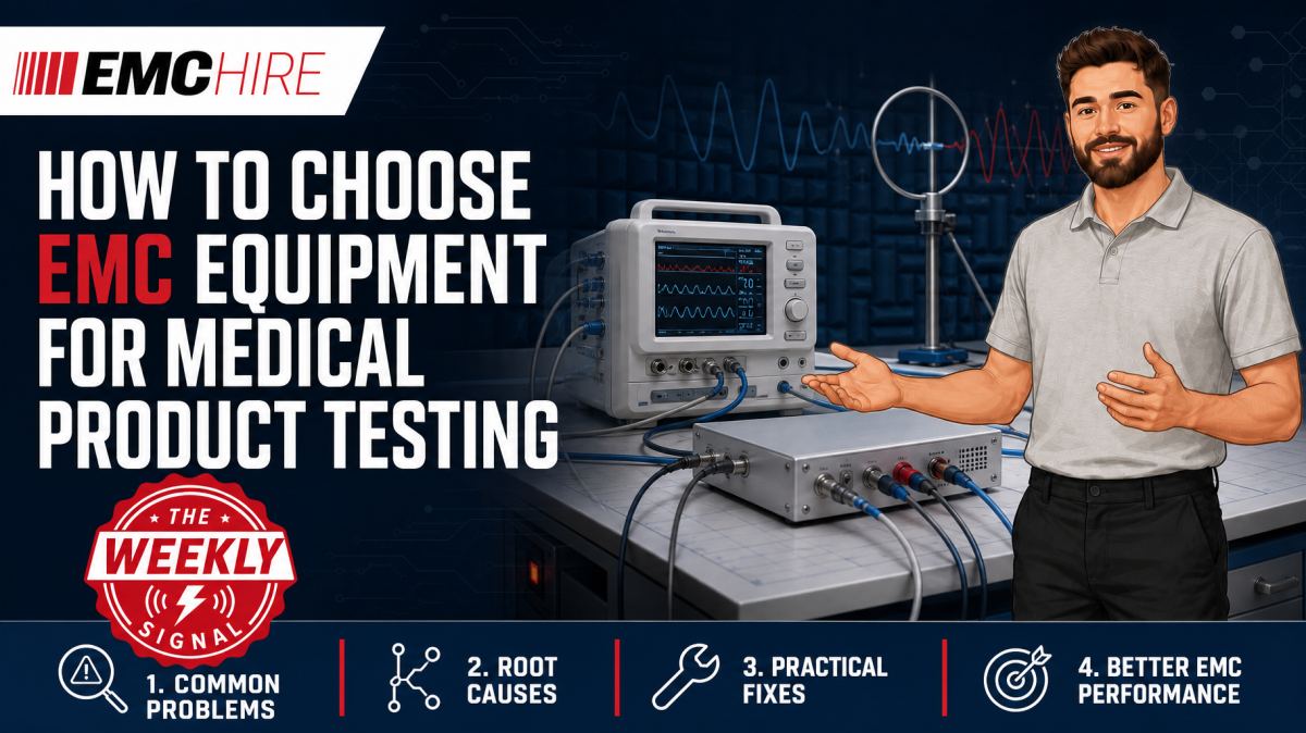
A medical EMC test setup can produce convincing plots while still being technically wrong. The usual cause is not the receiver or amplifier, but a mismatch between the product standard, coupling path, equipment capability and physical test arrangement.
Selecting medical EMC equipment therefore starts with the test plan, not a catalogue. The equipment under test, intended electromagnetic environment, applied parts, cable set, power architecture, operating modes and performance criteria all affect what must be generated, measured and monitored.
Start with the medical product requirements
IEC 60601-1-2 is widely used as the collateral EMC standard for medical electrical equipment and systems. It calls upon a range of basic emissions and immunity methods, but the applicable edition, national adoption, test levels and product-specific requirements must be confirmed for each project. Particular standards within the IEC 60601 series may modify or supplement the EMC expectations for a specific device.
The intended use environment matters. Equipment intended for professional healthcare facilities may not have the same risk assumptions as equipment intended for home healthcare or certain special environments. A test laboratory should also consider whether the device contains an intentional radio, whether other radio regulations apply, and whether foreseeable electromagnetic disturbances could affect basic safety or essential performance as defined by the applicable medical standards.
Before choosing hardware, record:
- The applicable standard editions and amendments.
- AC and DC power ports, signal ports, patient connections and enclosure ports.
- The intended electromagnetic environment and permitted cable lengths.
- Representative accessories, peripherals and applied parts.
- Normal operating modes and the modes most likely to expose EMC susceptibility.
- Pass or fail performance criteria and the monitoring method.
- Any product-specific, regional or customer requirements.
Leaving these decisions until equipment arrives often creates gaps. For example, a generator may cover the nominal RF frequency range but lack the power needed after amplifier compression, cable loss and coupling-device loss have been included.
EMC Hire's overview of medical device EMC compliance provides further context on planning an evidence-led test programme. The current published standards and official manufacturer documentation should always be checked for test levels, frequency ranges, configurations, limits and operating restrictions.
Medical EMC equipment for emissions measurements
Conducted emissions require the correct LISN
A LISN is used to present a defined impedance to the equipment's relevant power port, isolate the measurement from external RF noise and couple conducted disturbance voltage to an EMI receiver. It is an emissions device, not a conducted immunity coupler.
Selection depends on the supply type, voltage, current, number of phases, connector arrangement and applicable emissions method. Conducted emissions are commonly investigated over 150 kHz to 30 MHz, but that range must not be assumed without checking the applicable product requirements.
Current rating deserves particular attention with medical equipment containing heaters, pumps, compressors or switched-mode power supplies. A marginal LISN can overheat or create an unrepresentative voltage drop. Protective earth arrangements also need careful handling. Changing the earth path can alter common-mode current and move an emissions result by enough to hide or create a failure.
The measurement chain normally includes a suitable LISN, transient protection where appropriate, coaxial cable, attenuator or limiter if required, and an EMI receiver or analyser with the correct detector functions. Peak scanning is useful for diagnosis, while quasi-peak and average detectors are applied where required by the relevant emissions standard. Receiver bandwidth must follow the specified method rather than an analyser's convenient default.
Radiated emissions depend on more than antenna bandwidth
An antenna must cover the required measurement range with known antenna factors and suitable calibration data. The wider setup may require a preamplifier, low-loss cable, mast, turntable, characterised site and compliant receiver. Radiated emissions commonly begin at 30 MHz, although the upper frequency and detailed method depend on the product, its highest generated or used frequencies and the applicable requirements.
Antenna type, test distance and site geometry cannot be selected independently. Cable loss and preamplifier gain must be entered correctly into the measurement system. A 6 dB correction error remains a 6 dB error even if the displayed trace looks stable.
Ambient signals can also obscure a low-level medical device emission. Recording EUT-off ambient scans and investigating suspect frequencies prevents broadcast or local radio signals from being attributed to the product.
Selecting equipment for immunity testing
ESD generators need verified discharge behaviour
An ESD gun used for IEC 61000-4-2 testing must support the required contact and air-discharge voltages, discharge network and operating modes. The setup also needs the specified ground reference plane, coupling planes, discharge return cable and insulating supports.
Voltage capability alone is a poor selection criterion. The generator's discharge current waveform must be verified using the appropriate target and measurement arrangement at the required intervals. A damaged tip, incorrect discharge network or badly routed return cable can change the pulse delivered to the product.
Air discharge is particularly sensitive to approach speed, humidity, electrode geometry and surface condition. Contact discharge should be used at conductive points where the method requires it, while indirect discharges to coupling planes assess coupling into the equipment. EMC Hire provides further guidance on EN 61000-4-2 ESD testing and supplies suitable ESD generators for hire.
Radiated RF immunity requires an engineered power chain
Radiated immunity equipment usually includes an RF signal generator, power amplifier, directional coupler or power-monitoring arrangement, antenna, field probe and control software. The required field is expressed in V/m. It is not a conducted voltage level.
Amplifier selection should be based on the power required at the antenna input across the full band, including cable loss, mismatch, modulation headroom and amplifier compression. Quoting rated saturated output power is not enough. The test needs controllable linear power under the specified modulation conditions.
The antenna must be suitable for the immunity frequency range and power. A broadband antenna may simplify switching, but chamber size, field uniformity, antenna gain and amplifier demand still govern whether it is a sensible choice. Field uniformity calibration belongs to the test arrangement, not to the antenna in isolation.
Conducted RF and transient immunity use different coupling devices
IEC 61000-4-6 conducted RF immunity typically uses a CDN where the port and cable arrangement permit it. Electromagnetic clamps or current-injection arrangements may be used where specified by the applicable method. A BCI probe should not be substituted simply because it fits around the cable. Bulk current injection is associated with particular automotive, military, aerospace and product-specific procedures, and it is not universally interchangeable with a CDN.
Electrical fast transient or burst testing requires a suitable generator and the prescribed coupling method, which may include direct coupling to power ports and a capacitive coupling clamp for applicable signal cables. Surge testing uses a surge generator and defined coupling or decoupling networks. Combining these functions in one platform can be convenient, but each generator output, coupling network rating and port configuration still needs to match the test plan.
Voltage dips and interruptions require a source and switching arrangement able to reproduce the specified residual voltage and timing while supplying the EUT load. Power-frequency magnetic-field immunity uses a suitable induction coil and field-monitoring approach. Neither test should be inferred from a generic claim that a platform covers IEC 61000-4-x testing.
Typical scenario
Consider an illustrative patient-monitoring product powered by an external AC/DC adaptor. It has analogue patient leads, Ethernet, USB, an internal processor and a display. The development team wants pre-compliance evidence before committing to a formal programme.
The likely emissions setup includes an appropriate LISN for the adaptor's AC input, an EMI receiver, transient protection and a radiated measurement system with suitable antennas. The immunity package may include an ESD gun, radiated RF signal generator and amplifier chain, field probe, conducted RF generator with suitable CDNs, and transient generators selected for the applicable ports.
The patient leads create a difficult decision. They may behave as efficient common-mode antennas, but their treatment must follow the relevant medical product requirements and test plan. Substituting shorter leads for convenience could suppress a real coupling mechanism. Coiling excess cable into a compact bundle may also alter its resonances and produce data that cannot be compared with formal testing.
Monitoring is equally significant. A display that remains illuminated does not prove that measurements, alarms, communications or stored data remain acceptable. The engineering team needs an observable performance definition linked to the device's risk analysis and intended function.
Early testing allows the team to identify whether an ESD reset originates at an enclosure seam, patient cable or user interface before tooling is frozen. Calibrated engineering data can then guide filtering, shielding, bonding and firmware recovery work. These results improve confidence but do not automatically demonstrate compliance.
EMC Hire can support this work through a bundled equipment hire, practical setup advice, accessible pre-compliance testing, on-site testing or a booking at its medical device EMC test facility. Formal compliance testing may also be provided where appropriate for the conformity route, without implying that testing alone completes the manufacturer's obligations.
Calibration, validation and evidence quality
Medical test laboratories need more than an in-date label. Calibration scope, measurement uncertainty, transducer factors, cable losses and functional checks all affect whether the resulting evidence is defensible.
EMC Hire uses test equipment with calibration traceable through an appropriate ISO/IEC 17025 accredited calibration provider. The accreditation relates to the relevant calibration laboratory or activity, not to the physical instrument. Suitable traceability supports repeatability, comparison between development and formal measurements, and confidence during engineering or regulatory review.
Daily or pre-test checks remain worthwhile. Confirm generator output, receiver noise floor, interlock operation, cable continuity, amplifier gain and probe response as appropriate. Calibration does not detect a coaxial cable damaged yesterday.
For CE marking, UKCA marking or another self-certification route where applicable, the manufacturer remains responsible for identifying the legislation, standards, conformity assessment process and documentation requirements. Robust test records may support the technical file, EMC risk assessment, Declaration of Conformity, mitigation evidence and stakeholder review, but no individual test result guarantees regulatory acceptance or market access.
When to Hire EMC Equipment
Hiring is technically attractive when a laboratory needs a specific generator, antenna or amplifier for a defined project rather than a permanent capability. It avoids committing capital to equipment whose frequency range, current rating or coupling accessories may be unsuitable for the next programme.
Short medical development peaks also place unusual demands on internal laboratories. A hired bundle can add capacity without creating long-term storage, servicing and calibration overheads. This is particularly useful when several prototypes must be debugged before a fixed formal test date.
The bundle should be engineered as a system. Hiring an amplifier without checking antenna power handling, cable loss, directional coupler range and control compatibility merely relocates the problem. Supplying the test plan, EUT power details, port list and required test window allows EMC Hire's engineering team to help select a coherent package.
Where equipment ownership would be used infrequently, hire also reduces obsolescence risk. Standards, programmes and product architectures change. A laboratory that buys narrowly specified equipment may carry its maintenance costs long after it stops matching active work.
Common EMC Testing Mistakes to Avoid
Treating cable layout as housekeeping
Patient leads, mains cables and data cables form part of the coupling path. Moving them between runs changes radiated emissions and immunity response, undermining repeatability. Photograph positions, record exposed lengths and reproduce the specified arrangement.
Using the wrong LISN or CDN
A LISN measures conducted disturbance voltage on a relevant power port. A CDN injects conducted RF immunity onto an applicable cable. Confusing their roles produces an invalid setup rather than a useful approximation.
Selecting an amplifier from headline wattage
An amplifier may meet its advertised maximum power yet compress at the operating point needed for modulated immunity testing. The resulting field can be distorted or unstable. Assess linear output across the band and include every downstream loss.
Ignoring EUT operating modes
Medical equipment can emit differently during charging, pumping, wireless transmission, alarm activity or display updates. Immunity faults may only appear during a particular measurement cycle. A benign idle mode creates false confidence.
Failing to preserve test records
Frequency sweeps without cable photographs, software versions, accessory details, detector settings or observed performance are hard to reproduce. Weak records also make development data difficult to compare with later formal testing.
Frequently Asked Questions (FAQs)
Can one medical EMC equipment bundle cover every IEC 60601-1-2 test?
Not safely by assumption. Supply ratings, port types, frequency coverage, field levels, chamber characteristics and product-specific requirements vary. Build the bundle from a reviewed test plan and confirm the latest applicable editions.
Is a spectrum analyser sufficient for conducted emissions pre-compliance?
It can assist diagnosis if protected and configured correctly, but formal-style measurements may require an EMI receiver with the specified CISPR detectors, bandwidths and overload performance. The LISN and measurement protection must also suit the EUT supply.
How much amplifier power is needed for radiated immunity?
There is no universal wattage. Required power depends on target field strength, antenna gain, distance, chamber loading, cable loss, mismatch and field-uniformity calibration. Select from measured system performance with adequate linear headroom.
Can pre-compliance results be included in the technical file?
Calibrated, well-documented engineering results may support the technical file and risk-based justification. Their evidential weight depends on the setup, method and applicable conformity route. Pre-compliance data should not be represented automatically as formal proof of compliance.
When is an accredited laboratory required?
That depends on legislation, contractual conditions, customer expectations and the chosen conformity route. Some medical products may use self-certification where permitted, while particular programmes or stakeholders may require testing by an appropriately accredited laboratory. The responsible manufacturer should confirm the requirement.
Discuss the test setup before booking equipment
If you are defining a medical EMC equipment package, send EMC Hire the test plan, applicable standards, EUT supply details, port list, cable configuration and required test window. The engineering team can discuss equipment hire, on-site testing, pre-compliance support, formal compliance testing where appropriate, or space at the EMC Hire test facility.
Call +44 (0)1462 817111 or email sales@emchire.co.uk to review the setup or request an equipment hire quotation.
Disclaimer: Content is for informational purposes only and does not constitute formal engineering or regulatory advice. Always verify testing procedures against current official standards (e.g., ISO, MIL-STD, DEF STAN). EMC Hire Limited accepts no liability for outcomes resulting from the use of this information.