

How to interpret automotive EMC failures by pulse type
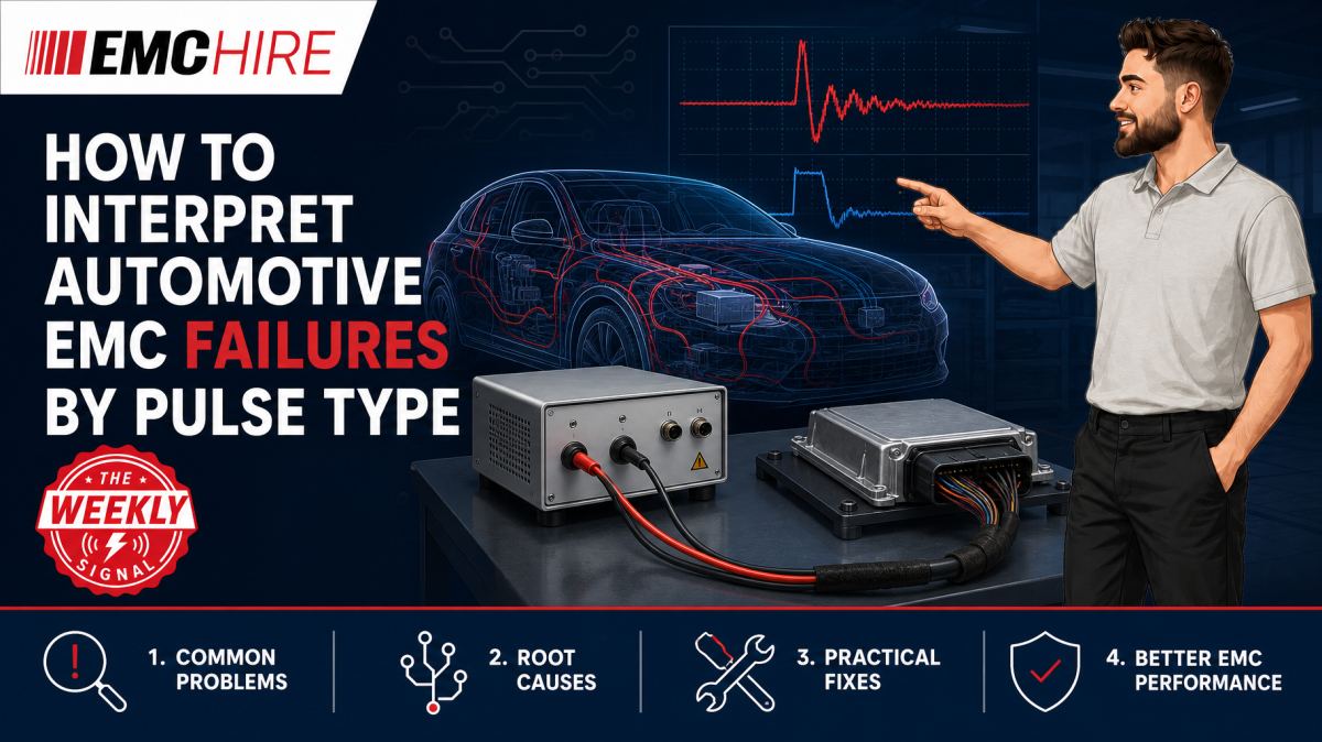
A transient failure timestamp tells you when the EUT stopped behaving. The pulse polarity, coupling path and recovery signature tell you why.
Automotive EMC failures are often misdiagnosed because the observed symptom is treated as the fault mechanism. A reset may result from undervoltage, processor pin injection, reference movement or a protection device entering conduction. Those mechanisms require different corrective actions, even if the vehicle-level symptom looks identical.
Start with the disturbance mechanism, not the pulse number
Pulse designations are useful shorthand, but they are not a diagnosis. The first task is to classify the electrical stress applied to the equipment under test, or EUT: polarity, amplitude, source impedance, rise time, duration, repetition and injection path. The applicable edition of ISO 7637, ISO 16750, an OEM specification or a programme-specific test plan must then be checked for the actual waveform and setup.
This distinction matters because nominally similar pulse names can appear with different severities or configuration requirements across customer specifications. Reproducing a remembered pulse setting from another programme can produce an invalid test and send the investigation towards the wrong protection network.
For first-pass triage, automotive supply disturbances can be grouped into several broad mechanisms:
- Negative supply transients associated with interruption of current in inductive circuits.
- Positive supply transients caused by switching and redistribution of stored energy.
- Fast positive and negative switching transients with high-frequency content.
- Longer-duration overvoltage events, including applicable load-dump simulations.
- Supply dips, interruptions, ramps and starting profiles that test functional behaviour rather than only component survival.
ISO 7637-2 is commonly associated with conducted electrical transients along supply lines, while ISO 16750-2 addresses electrical loads and supply conditions at a broader level. Their scope, current editions and relationship to an OEM requirement must be confirmed rather than assumed. Neither document should be treated as a substitute for the product-specific or contractual test plan.
What the main pulse categories reveal
Negative pulses expose reverse stress and collapsing rails
A negative pulse can drive the input below local ground and force current through reverse-polarity protection, suppression devices, controller protection structures and unintended return paths. A total reset during the pulse may simply indicate that the downstream rail fell below the processor's operating or brownout threshold. That is different from damage caused by excessive reverse voltage.
Measure both sides of the input protection stage. If the harness input follows the generator waveform but the protected rail remains controlled, the external protection is probably doing its job. If the protected rail collapses despite adequate input capacitance, examine diode or MOSFET reverse protection behaviour, DC-DC converter lockout thresholds and the impedance between the bulk capacitor and regulator.
Ground-referenced communication lines also deserve attention. During a negative supply event, a powered network node elsewhere in the system may feed the EUT through CAN, LIN, Ethernet or discrete I/O protection structures. The module may then be partially powered through a signal pin. This can produce a latched state that disappears when the communications harness is disconnected, revealing the real coupling path.
Positive pulses reveal clamping and energy-management limits
Short positive pulses initially test the response of the input filter, transient suppressor and regulator. The peak voltage at the connector is not the whole story. Source impedance and pulse duration determine the energy delivered to the EUT and whether a suppressor clamps briefly or enters a damaging thermal regime.
A functional upset with no visible damage often points to rail overshoot, regulator control-loop disturbance or ground movement. Permanent low input resistance after testing suggests a failed suppressor, input semiconductor or capacitor. Replacing the suppressor with a higher-voltage part may stop it failing but can expose the DC-DC converter to a voltage beyond its rating. Protection coordination must be assessed as a system.
If the upset occurs on the falling edge rather than at the positive peak, inspect the supply recovery. Some converters shut down during overvoltage and restart into an unfavourable load condition. The apparent positive-pulse failure is then an undervoltage or sequencing failure during recovery.
Fast switching pulses find layout weaknesses
Fast positive and negative transient families contain more high-frequency energy than slower supply variations. Their behaviour is dominated by parasitic inductance, capacitance and physical layout. A protection component selected from a low-frequency schematic may be ineffective if it sits several centimetres from the connector.
Long tracks between the connector, suppressor and chassis or power return add inductance. The voltage developed across that inductance can allow a fast edge to reach the regulator or couple into nearby reset, crystal, sensor and communication traces before the suppressor conducts effectively.
Failures that change when a probe, oscilloscope ground lead or harness position is moved are strong evidence of a high-frequency coupling problem. They are also a warning that the measurement setup is perturbing the circuit. Use appropriately rated differential or isolated measurement techniques, keep probe loops small and document every connection.
Long-duration overvoltage tests thermal and safe-state design
Load-dump and other sustained overvoltage conditions differ from fast transient tests. The longer energy delivery can heat suppression components, connectors, tracks and protection semiconductors even when the peak clamp voltage appears acceptable.
A module that survives one event but fails after repetition may have inadequate thermal recovery time or poor energy sharing. Conversely, a module that enters a safe shutdown and recovers within the permitted performance criterion may behave acceptably, depending on the applicable requirement. The relevant ISO 16750-2 or OEM test conditions, EUT operating state and functional classification must be checked.
Do not infer energy capability from a transient voltage suppressor's nominal stand-off voltage. Pulse shape, source impedance, component temperature, production tolerance and mounting conditions all affect the result.
Use the failure signature to narrow the coupling path
The same supply disturbance can reach sensitive circuitry through several paths. Capturing only the generator monitor output leaves most of the diagnostic picture missing.
Useful correlated measurements may include the EUT connector voltage, protected internal supply, processor reset, watchdog output, key communication lines and supply current. The measurement system must have adequate bandwidth, isolation and voltage rating for the event. Probe capacitance and ground inductance can alter fast waveforms or create a hazardous return path.
Failure timing provides a useful first-pass map:
- Failure at the leading edge: suspect capacitive coupling, parasitic inductance, poor suppression placement or direct pin injection.
- Failure near the pulse peak: examine clamp voltage, regulator absolute maximum ratings and overvoltage lockout.
- Failure after sustained exposure: consider thermal stress, capacitor discharge, regulator shutdown or software timeout.
- Failure on the trailing edge: investigate rail undershoot, converter restart, sequencing and inductive recovery.
- Failure only with communications connected: check signal-line back-powering, reference displacement and network return paths.
- Failure after multiple repetitions: look for cumulative heating, watchdog-state corruption or protection degradation.
Software logs add value only if their timing can be related to the applied pulse. A generic watchdog-reset record does not distinguish supply collapse from electromagnetic injection into a clock or reset line.
Typical scenario
Consider an illustrative 12 V control module that resets during a negative conducted transient but passes slow supply-dip testing. The setup includes a suitable automotive transient generator, the specified artificial network or source arrangement, the production-intent harness, representative loads and monitoring of the module's functional outputs.
The test team must first confirm generator verification, pulse polarity, source impedance, repetition, battery support arrangement and EUT operating mode against the applicable specification. A reversed connection or incorrect network can create a waveform that looks plausible on the generator display but is wrong at the EUT connector.
Correlated probing then shows whether the protected rail falls with the external pulse. If it does, the investigation moves towards hold-up capacitance, reverse protection and regulator lockout. If the rail remains stable but reset asserts, attention shifts to reset-line coupling, ground bounce or external I/O paths. Disconnecting interfaces one at a time, where technically safe and permitted by the test plan, can identify the dominant coupling path.
Early investigation on an accessible prototype allows protection placement, return paths and firmware recovery to be changed before enclosure and harness designs are frozen. It does not prove compliance, but it reduces the chance of paying for formal testing merely to discover a layout fault.
EMC Hire can support this work through automotive EMC testing support, appropriate automotive test systems, equipment hire, facility access and on-site investigation. Test equipment used for relevant measurements is calibrated with traceability through an appropriate ISO/IEC 17025 accredited calibration provider, supporting repeatability and comparison between development and formal testing.
When to Hire EMC Equipment
Automotive transient systems are specialised assets. A generator suitable for one pulse family, voltage class or source impedance is not automatically suitable for another OEM programme. Hiring allows a team to obtain the required generator, coupling network and monitoring equipment for a defined test window without committing capital to a system that may not suit the next platform.
This approach is particularly useful during prototype peaks, regression campaigns and fault investigations where engineering access matters more than continuous ownership. It also avoids long-term storage, servicing and calibration administration. Suitable transient and surge equipment can be selected around the required method rather than around whatever instrument happens to be available internally.
Ownership risk is often underestimated. Generator options, amplifier capability, network ratings and software support can restrict future use. Hiring transient generators and related test equipment for an identified programme reduces the risk of buying a technically unsuitable configuration.
Where internal resources are constrained, EMC Hire can also help with pre-compliance engineering, on-site testing, test facility bookings and formal compliance testing where appropriate. For defence, automotive and aerospace programmes, final evidence may need to come from an appropriately accredited laboratory where contractual or programme requirements demand it.
Common EMC Testing Mistakes to Avoid
Trusting the generator display instead of the EUT terminals
Cable impedance, artificial networks, support supplies and EUT loading alter the delivered waveform. Verification at the specified point is needed. Otherwise, a pass may represent under-testing and a failure may result from an excessively severe or malformed pulse.
Changing harness geometry without recording it
Fast transient coupling is sensitive to harness length, separation, return routing and proximity to conductive structures. An undocumented cable movement can remove a failure without correcting the design, leaving no reproducible evidence trail.
Testing an unrepresentative operating mode
An idle module may draw less current, disable switching converters or leave interfaces inactive. The protection network and software response can therefore differ from normal vehicle operation. Exercise the modes, loads and communications required by the test plan.
Using unsuitable probes or long ground leads
A long oscilloscope ground lead adds parasitic inductance and can display ringing that is largely a measurement artefact. It may also create a new coupling path. Probe selection, isolation, voltage rating and connection geometry must suit the transient being observed.
Assuming every reset is an undervoltage event
Reset-line injection, oscillator disturbance, watchdog expiry and communication back-powering can all produce the same visible symptom. Without correlated rail, reset and interface measurements, component changes become guesswork.
Failing to preserve the test record
Record the pulse configuration, generator and network identification, calibration status, EUT hardware and software revision, harness arrangement, operating mode, loads, monitoring criteria and recovery behaviour. Weak records make repetition difficult and provide poor support for a technical file, Declaration of Conformity, EMC risk assessment or customer review.
Frequently Asked Questions (FAQs)
Can the pulse number alone identify the failed component?
No. It identifies a waveform family, not the internal coupling mechanism. Polarity, duration, source impedance, failure timing and correlated internal measurements are needed before narrowing the fault to a suppressor, regulator, processor or interface.
Why does a module fail only when connected to the vehicle network?
The network may provide an alternative current return or back-power the module through transceiver protection structures. It may also shift the local ground reference. Compare tests with representative communications and loads, following the permitted configuration in the applicable test plan.
Does passing pre-compliance transient testing prove conformity?
No. Pre-compliance work provides engineering evidence and improves confidence, but formal requirements depend on the applicable legislation, product requirements, OEM specification and conformity route. The manufacturer or responsible economic operator remains responsible for confirming these obligations and maintaining the technical file.
Should ISO 7637 or ISO 16750 be used?
That depends on the product, electrical architecture, customer specification and disturbance being assessed. They cover related but distinct electrical and transient conditions. Verify the latest active editions, test levels, waveform definitions, configurations, performance criteria and documentation requirements.
What is the most useful measurement during a reset?
There is rarely one measurement. A time-correlated view of connector voltage, protected rail, reset state and functional output usually provides more diagnostic value than a single high-bandwidth trace. Add interface monitoring where back-powering or reference displacement is suspected.
Can automotive transient tests be performed on site?
Often they can, provided the site can support the required equipment, safety controls, earthing, power, environmental conditions and test configuration. A setup review is needed before deciding whether on-site testing or a controlled facility is the better option.
Plan the investigation around evidence
A useful automotive transient investigation should explain not only which pulse caused a failure, but when the failure started, which coupling path carried the disturbance and how the EUT recovered. That evidence supports design decisions, mitigation records, customer discussions and a more defensible formal test programme.
To discuss equipment selection, request a hire quotation, arrange on-site testing, book space at the EMC Hire test facility or plan pre-compliance or formal compliance work, contact the EMC Hire engineering team on +44 (0)1462 817111 or email sales@emchire.co.uk.
Disclaimer: Content is for informational purposes only and does not constitute formal engineering or regulatory advice. Always verify testing procedures against current official standards (e.g., ISO, MIL-STD, DEF STAN). EMC Hire Limited accepts no liability for outcomes resulting from the use of this information.