


How enclosure design affects radiated emissions
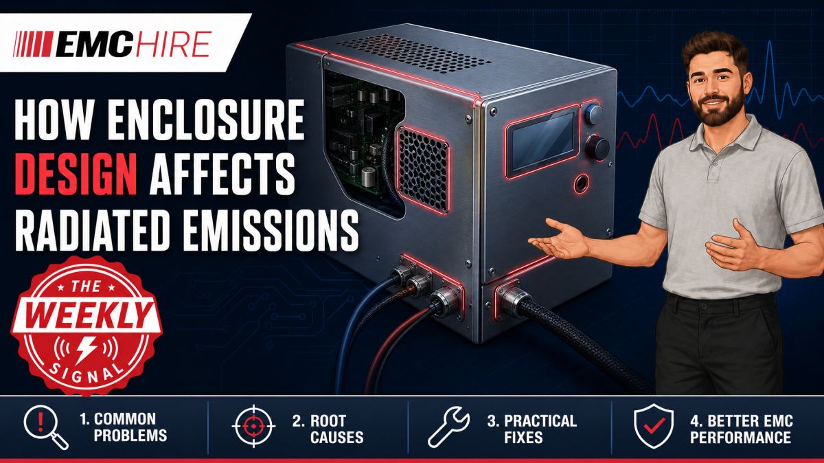
A conductive enclosure can look completely closed in CAD yet behave as an efficient radiator once seams, vents, displays and cable exits are added.
Enclosure EMC is therefore not just a shielding-material problem. Emission performance depends on current return paths, aperture dimensions, joint impedance, internal field distribution and the way cables interact with the housing.
Why enclosure geometry changes radiated emissions
Radiated emissions normally originate from time-varying currents and voltages within the equipment. Fast digital edges, switch-mode power stages, clock networks, motor drives and RF circuitry can excite PCB traces, heatsinks, internal wiring and enclosure panels. The resulting electromagnetic energy may then couple through openings or drive common-mode current onto external cables.
A metal housing can reduce this coupling when it provides a continuous, low-impedance boundary. Real housings are rarely continuous. They contain seams, fasteners, ventilation holes, controls, display windows and removable covers. Each feature changes the available current path and can reduce shielding effectiveness at particular frequencies.
The relevant dimension is electrical length, not simply physical size. A 30 mm slot may appear mechanically insignificant, but its behaviour changes as frequency rises and wavelength falls. Long narrow slots can be especially troublesome because the longest dimension largely governs their coupling behaviour. Several small circular holes will not necessarily behave like one opening of the same total area because aperture shape, spacing and surrounding current paths also matter.
Near-field coupling complicates the picture. A noisy inductor placed a few millimetres behind a vent can couple magnetic flux through the opening even when a far-field wavelength calculation suggests that the aperture is small. Moving the source, rotating it or adding a local shield may produce more benefit than making a minor change to the external panel.
Seams are RF components
A mechanical joint is not automatically an RF bond. Paint, anodising, oxide layers, adhesive films and loose fastener spacing can create significant impedance between adjacent panels. At higher frequencies, current concentrates near surfaces and seeks the lowest-impedance path around an opening. If that path is interrupted, voltage develops across the seam and the seam can radiate.
Fastener spacing needs to be considered against the highest frequency of concern and the mechanical stiffness of the panels. Widely spaced screws can leave sections of a cover electrically open between fixing points. Panel distortion makes this worse by producing inconsistent pressure along a conductive gasket.
Conductive gaskets can improve seam continuity, but only when the contact surfaces, compression range and environmental conditions are controlled. Excessive compression can permanently damage some gasket types. Too little compression leaves local discontinuities. Corrosion between dissimilar metals may gradually increase contact resistance, so a prototype that passes when new may not represent aged production hardware.
Bonding straps also have limitations. A long pigtail bond adds inductance and may be ineffective at RF even though it measures close to 0 Ω with a handheld multimeter. Broad, short bonding features generally provide lower high-frequency impedance than long round wires. Four-terminal resistance measurements can help assess low-frequency joint resistance, but they do not by themselves characterise RF bonding performance.
Apertures, vents and displays
Ventilation often creates the largest opening in an enclosure. Thermal and EMC requirements can therefore pull the design in opposite directions. A small number of long slots may provide adequate airflow but poor shielding at frequencies where the slots become electrically significant.
Alternatives include arrays of smaller holes, conductive mesh, honeycomb vent panels and waveguide-below-cut-off structures. Selection depends on airflow resistance, frequency range, mechanical depth, contamination risk and cost. Honeycomb vents can provide good attenuation when correctly bonded around their perimeter. Poor perimeter contact allows current to bypass the intended structure and can negate much of the shielding benefit.
Displays and polymer windows need similar treatment. A conductive coating or mesh is only useful when it is electrically terminated to the enclosure with a suitably low-impedance connection. Connecting a shielded window at one corner through a narrow trace can leave most of its perimeter electrically floating at RF.
Large apertures should also be kept away from strong internal sources. An illustrative example is a DC-DC converter positioned directly behind a side vent. The magnetic field from the switching loop can couple through the vent, while switch-node capacitance drives nearby metalwork. Moving the converter inward, reducing the switching-loop area and improving its local return path may lower emissions without changing the vent itself.
Cable penetrations can bypass the enclosure
A well-shielded box can still fail if common-mode current reaches an external cable. The cable then becomes the effective antenna, often producing broad emission peaks related to cable length and installation geometry.
Cable shields should normally be terminated in a manner consistent with the required frequency range and product architecture. A 360-degree shield termination at the enclosure entry generally has much lower RF impedance than a long drain wire. The pigtail inductance can prevent high-frequency shield current from transferring effectively to the chassis, forcing current onto unintended paths.
Filters should be located close to the enclosure penetration. Placing a filter deep inside the product leaves an unfiltered conductor running through the internal field region. That conductor can pick up noise after the filter and carry it outside. Filter input and output wiring must also be separated. Bundling both sides together introduces capacitive and inductive recoupling around the filter.
Conducted common-mode noise and radiated emissions are closely related. Measuring the power port using an appropriate LISN can reveal noise that may later drive attached leads. EMC Hire provides information on conducted emissions measurement systems and the correct role of line impedance stabilisation networks. A LISN is used for relevant conducted emissions measurements, not conducted immunity testing.
Designing a representative radiated emissions investigation
Development measurements should reproduce the intended cable set, enclosure fixings, software activity and peripheral loading as closely as practical. Testing an open chassis with short laboratory leads may help locate sources, but it does not predict the behaviour of a fully assembled product with long external cables.
Near-field probes are useful for finding leakage around seams, connectors and vents. They provide comparative diagnostic data rather than a direct prediction of far-field compliance. Probe orientation and distance must remain consistent because a few millimetres of movement can substantially change the response. Suitable antennas and near-field probes support both local investigation and defined radiated measurement work.
For formal or pre-compliance radiated emissions measurements, antenna type, test distance, site characteristics, detector, measurement bandwidth and EUT configuration must follow the applicable product or product-family standard. Radiated measurements commonly begin at 30 MHz, but that is not universal. The upper frequency depends on the product, its highest internal frequencies and the applicable requirements.
CISPR 32 may be relevant to multimedia equipment, while CISPR 11 addresses certain industrial, scientific and medical equipment. Product scope must be checked rather than selected from the test method alone. Always verify the latest active edition, limits, frequency range, operating modes, cable configuration and documentation requirements. Standards issued through bodies such as the IEC should be read in their current published form rather than replaced by informal summaries.
EMC Hire's radiated emissions system information provides a starting point for selecting compatible receivers, analysers, antennas, preamplifiers and accessories.
Typical scenario
Consider an illustrative industrial controller containing a processor board, Ethernet interface and switched power converter. Early bench scans with the electronics exposed show local activity around the processor clock harmonics. The first metal enclosure reduces some emissions, but a new peak appears when the painted lid and external Ethernet cable are fitted.
The engineering team needs to determine whether energy is escaping through the lid seam, coupling through the vent, or driving common-mode current onto the cable. A useful investigation would compare repeatable configurations: lid removed, lid fitted, temporary conductive bonding applied, vent locally covered with conductive material, and cable common-mode current observed with a suitable current probe. Near-field scanning around the seam and connector can then identify likely leakage paths.
Temporary modifications must be interpreted carefully. Copper tape may demonstrate that seam impedance matters, but it does not prove that a production gasket will give identical performance after environmental ageing. Likewise, clamping ferrite around a cable may identify a common-mode mechanism without establishing the final component specification.
Early investigation gives mechanical and electronics engineers room to change connector bonding, fastener spacing, PCB placement or filter layout before tooling is committed. EMC Hire can support this work through equipment hire, accessible pre-compliance testing, on-site measurements and test-facility access. Where appropriate, formal compliance testing can then produce engineering evidence for the technical file, Declaration of Conformity, EMC risk assessment and self-certification process. The manufacturer remains responsible for determining the applicable legislation, standards and conformity route.
When to Hire EMC Equipment
Hiring is often sensible when enclosure EMC work is concentrated into a short prototype or design-verification window. A team may need a receiver, antenna, near-field probes, current probes and a LISN for several weeks, but have no continuing requirement once the mechanical design is frozen.
This avoids capital expenditure on equipment that may not suit the frequency range or standards used by the next programme. It also reduces storage, servicing and calibration overheads. During project peaks, hired equipment can expand internal capability without forcing engineers to queue for a shared analyser or delay a test campaign.
Equipment selection still needs care. An analyser with inadequate frequency coverage, an unsuitable antenna or a probe lacking characterised transfer data can produce misleading results. EMC Hire can help define a compatible system for a stated measurement objective and test window, rather than treating each instrument as an isolated item.
Where calibration affects recorded measurements, EMC Hire uses test equipment with calibration traceable through an appropriate ISO/IEC 17025 accredited calibration provider. Suitable traceable calibration supports repeatability, comparison between development and formal measurements, and a stronger evidence trail. It does not make the instrument or EMC Hire's facility itself ISO/IEC 17025 accredited.
Common EMC Testing Mistakes to Avoid
Changing cable positions between measurements
Cable geometry strongly affects common-mode radiation. Moving a lead while changing a gasket creates two variables, so the apparent improvement cannot be attributed confidently to either change. Photograph cable routes and use non-conductive supports or position markers.
Testing an unrepresentative operating mode
An idle processor, inactive communications port or lightly loaded converter may miss the worst emission state. Exercise interfaces, power states and processing loads using a documented sequence that can be repeated during formal testing.
Relying on peak scans as final evidence
Peak detection is useful for fast exploratory scans, but applicable limits may require quasi-peak or average measurements with specified bandwidths. Using the wrong detector or resolution bandwidth can create false confidence or unnecessary failures.
Ignoring contact finishes
Bonding a bare prototype enclosure and then painting production mating surfaces changes seam impedance. Masking, conductive finishes, gasket lands and fastener contact areas must be represented in the tested build.
Covering an aperture without controlling the boundary
A loose sheet of foil over a vent does not reproduce a continuously bonded shield. Leakage around the foil perimeter can dominate the result, leading the team to reject an otherwise useful aperture treatment.
Failing to record the configuration
Missing photographs, software versions, accessory details, cable lengths or lid torque values make a result difficult to reproduce. That weakens fault diagnosis and leaves an unsuitable compliance evidence trail.
Frequently Asked Questions (FAQs)
Is a thicker metal enclosure always better for radiated emissions?
No. Once the material provides adequate attenuation for the relevant field mechanism, seams and penetrations often dominate. Increasing wall thickness will not repair a poorly bonded lid or a pigtail cable-shield termination.
Are many small ventilation holes better than one long slot?
Often, but not automatically. The longest aperture dimension, spacing, panel currents, vent depth and source proximity all matter. Thermal pressure drop and mechanical requirements must also be assessed.
Can near-field probes prove compliance?
No. They are diagnostic tools for locating and comparing local fields. Compliance evidence requires the applicable measurement method, site, antenna, distance, detectors, bandwidths and documented EUT configuration.
Should cable shields be bonded at one end or both ends?
There is no universal answer. High-frequency shielding usually benefits from low-impedance termination to chassis, while low-frequency ground-loop, safety and functional requirements may influence the architecture. The decision should be based on frequency, cable function, installation and the applicable product requirements.
Can pre-compliance testing replace formal testing?
Pre-compliance testing helps expose problems, compare design changes and gather calibrated engineering data, but it does not automatically prove compliance. Formal testing and documentation should follow the applicable conformity route and product-specific requirements.
When should enclosure testing begin?
Start before tooling is fixed. Representative mock-ups, temporary seam treatments and cable-current measurements can identify coupling mechanisms while connector placement, bonding features and vent geometry are still changeable.
Planning the next measurement stage
Enclosure EMC problems are usually cheaper to resolve when mechanical and electronics teams investigate them together. A shielding change cannot compensate reliably for uncontrolled cable current, and a PCB filter may underperform if the enclosure bond forces current through a long inductive path.
To discuss equipment selection, an equipment hire quotation, on-site testing, pre-compliance work, formal compliance testing where appropriate, or a booking at the EMC Hire test facility, contact the engineering team on +44 (0)1462 817111 or email sales@emchire.co.uk. A short review of the product architecture, frequency range, enclosure construction and intended standards can prevent the wrong measurement system or test configuration being chosen.
Disclaimer: Content is for informational purposes only and does not constitute formal engineering or regulatory advice. Always verify testing procedures against current official standards (e.g., ISO, MIL-STD, DEF STAN). EMC Hire Limited accepts no liability for outcomes resulting from the use of this information.