

ISO 11452-4 harness excitation testing explained
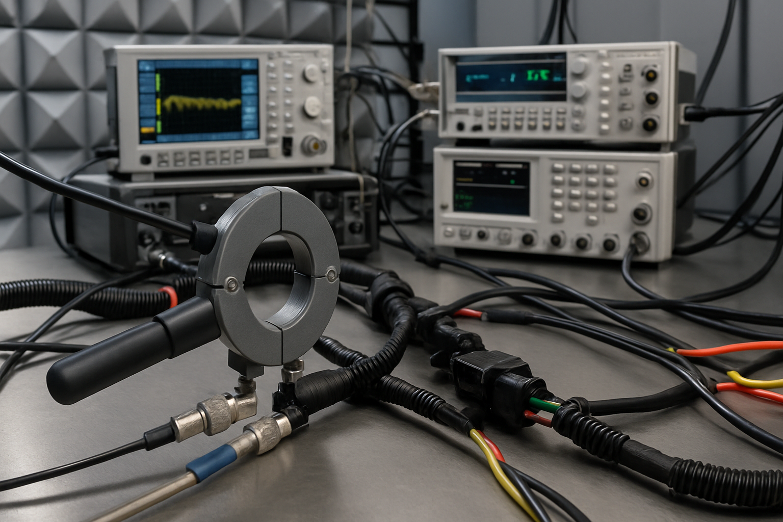
A bulk current injection test can look stable on the RF amplifier display while the harness current, and therefore the stress applied to the EUT, is materially wrong.
ISO 11452-4 addresses component-level automotive immunity using harness excitation methods. The test is intended to reproduce RF currents that may be induced onto vehicle wiring by transmitters and other electromagnetic sources. Its value lies in testing the cable harness as part of the coupling path, rather than treating the electronic control unit as an isolated enclosure.
What ISO 11452-4 covers
ISO 11452-4 forms part of the ISO 11452 series for electrical disturbance testing of road vehicle electronic components. It describes harness excitation methods, including bulk current injection and the tubular wave coupler method. The appropriate method, frequency range, severity, modulation, dwell time and performance criteria must come from the current standard, the applicable OEM specification and the agreed component test plan.
This distinction matters. ISO 11452-4 defines a component immunity method, not a universal vehicle acceptance limit. Automotive manufacturers frequently supplement or modify the base method through their own specifications. A supplier should not assume that satisfying a generic test configuration automatically satisfies every customer programme.
The wider ISO 11452 test method series includes other coupling mechanisms, such as absorber-lined chamber and stripline methods. Selecting between them requires an understanding of the product, harness architecture, intended RF environment and customer requirements.
Why the harness dominates the coupling path
At RF, a vehicle harness is not simply a collection of ideal conductors. Wire length, branching, shield termination, return paths, connector impedance and proximity to conductive structures all affect common-mode current. The harness can collect electromagnetic energy and deliver it directly to interface protection, PCB references and internal circuitry.
Bulk current injection, commonly abbreviated to BCI, uses an RF current injection probe clamped around the harness. The probe behaves as a transformer. RF power applied to its primary structure produces current in the enclosed conductors, while the harness and its return path form part of the secondary circuit.
The resulting current is not determined by amplifier power alone. Harness impedance changes with frequency and configuration, while the injection probe, fixture, monitoring probe and amplifier each have frequency-dependent behaviour. Standing waves and resonances can produce large changes in current for relatively small changes in frequency or cable position.
That is why a repeatable mechanical arrangement matters. Moving a branch, changing the height above the reference ground plane or replacing an unrecorded support material can shift resonances. A later retest may then expose a different susceptibility response even though the nominal test level is unchanged.
Bulk current injection setup and calibration
A typical BCI system comprises an RF signal generator, modulation source where required, RF power amplifier, directional coupler or suitable power monitoring arrangement, injection probe, calibration fixture and a current monitoring probe. The EUT, support equipment, artificial networks where specified, wiring harness and ground plane must be configured in accordance with the applicable test plan.
The injection and monitoring probes perform different jobs. The injection probe couples RF energy into the harness. A monitoring probe measures the resulting RF current without intentionally applying the stress. Using a probe outside its characterised frequency or current range can introduce measurement error, excessive insertion effects or heating.
Before testing the EUT, the injection chain is characterised using the prescribed calibration arrangement. The purpose is to determine the forward power needed to establish the required current in a known fixture across the test frequencies. That recorded power can then provide a controlled limit during the EUT test.
Two control concepts are commonly encountered in BCI procedures and customer specifications:
- A substitution approach applies forward power established during calibration, subject to the defined power limit and test procedure.
- A current-limited or closed-loop approach monitors harness current and adjusts drive within the permitted forward-power boundary.
These approaches are not interchangeable merely because the same equipment is used. Closed-loop control can drive substantially more amplifier power into a high-impedance or resonant EUT harness unless a calibrated forward-power limit is enforced. Conversely, applying calibration power without monitoring the actual harness current may hide poor coupling, probe saturation or a configuration error.
Calibration should include the complete RF path relevant to the measurement. Changing a coaxial cable, attenuator or injection probe after calibration alters insertion loss and can invalidate the stored forward-power table. Connector torque and damaged RF cables are less dramatic but equally capable of undermining repeatability.
EMC Hire uses test equipment with calibration traceable through an appropriate ISO/IEC 17025 accredited calibration provider where calibration is relevant to the measurement. Suitable traceability supports repeatability, comparison between development and formal testing, and a stronger engineering evidence trail. It does not remove the need for a valid system-level calibration and controlled test configuration.
Choosing between BCI and tubular wave coupling
The tubular wave coupler provides distributed coupling to a section of harness, rather than concentrating injection at one clamp position. It may be called up for frequencies and configurations where the applicable specification considers that method appropriate. The current edition of ISO 11452-4 and the customer test plan must be checked before selecting it.
BCI equipment should not be substituted for a tubular wave coupler simply because both methods excite the harness. Their field distribution, coupling behaviour, calibration and usable frequency ranges differ. Results from one method cannot automatically be treated as equivalent to results from the other.
Equipment selection therefore starts with the prescribed method. Amplifier output power alone is a poor selection criterion. Engineers also need to consider probe transfer impedance, amplifier bandwidth and compression, monitoring-probe range, signal-generator capability, modulation requirements, fixture ratings and the losses in the complete RF chain.
Interpreting automotive immunity performance
An immunity test is not judged solely by whether the EUT remains powered. Product functions must be monitored against the agreed performance criteria. Analogue drift, communication errors, false diagnostic trouble codes, sensor offset, output interruption and unintended actuator commands may all represent susceptibility, depending on the component and safety analysis.
Monitoring equipment can create its own RF path. Long oscilloscope leads, unfiltered communication cables and poorly bonded support equipment may couple energy into the EUT or carry it away. Fibre-optic links, filtered interfaces and carefully controlled auxiliary wiring can reduce this disturbance, but their use must remain representative of the approved setup.
Software state also matters. A controller tested in an idle diagnostic mode may draw different currents, switch different loads and exercise fewer interfaces than it does in service. That can conceal a susceptibility mechanism that appears when pulse-width-modulated outputs, network traffic or sensor acquisition are active.
Typical scenario
Consider an illustrative electronic control unit with several low-level sensor inputs, a CAN interface and two switched outputs. The automotive supplier has an OEM test plan calling for ISO 11452-4 bulk current injection before design validation.
The engineering team must define a representative harness, loads, operating modes, injection-probe position, monitoring method and functional pass criteria. The selected amplifier and probe combination must cover the required test range with enough usable power after cable, coupler and probe losses. A nominally powerful amplifier may still be unsuitable if its output compresses where the injection probe is least efficient.
Early pre-compliance work can reveal whether RF current is entering through sensor wiring, communication shielding, supply returns or connector references. Engineers can then evaluate changes such as common-mode filtering, shield termination, PCB return-path control or interface protection before tooling and validation schedules become restrictive.
Hiring the required current probes and injection clamps, amplifier and RF instrumentation can cover a defined development window without committing capital to equipment that may not suit the next OEM programme. It also avoids long-term storage, servicing and calibration overheads.
EMC Hire can support equipment selection, accessible pre-compliance investigation, automotive EMC testing, facility access and on-site work. Where final programme or contractual testing requires an appropriately accredited laboratory, that requirement should be established before the validation plan is approved.
When to Hire EMC Equipment
ISO 11452-4 systems are often needed in short, intense periods around prototype integration, design verification and fault investigation. Purchasing an amplifier before the required frequency coverage, probe efficiency and OEM methods are settled can leave a business owning an expensive but incomplete test chain.
Hire is particularly practical when different customer programmes specify different severity levels or harness methods. It allows the system to be matched to the current test window rather than an assumed future requirement. Additional equipment can also be brought in during project peaks without building a permanently underused internal laboratory.
Ownership costs extend beyond the initial instrument price. RF amplifiers require suitable power, cooling and storage, while probes, couplers and cables need controlled handling and periodic characterisation or calibration as appropriate. Hiring transfers much of that logistical burden while retaining access to a technically matched setup.
For development teams with an intermittent requirement, combining hire with conducted immunity testing support can be more defensible than assembling an unverified system from available laboratory parts. The aim is calibrated engineering data and a reproducible setup, not merely evidence that RF power was applied.
Common EMC Testing Mistakes to Avoid
Treating forward power as harness current
Forward power is an input condition, while induced current is the stress quantity associated with BCI. Confusing them can create false confidence, particularly around harness resonances or probe efficiency minima. Record both where the procedure requires them and enforce the applicable calibrated power limit.
Changing the harness after calibration or baseline work
Moving the harness, changing branch routing or altering its height above the ground plane changes common-mode impedance. The resulting test may no longer be comparable with earlier data, making a design change appear better or worse for purely geometric reasons.
Using the wrong current probe
A monitoring probe must have suitable bandwidth, transfer impedance, current capability and aperture. Applying an unverified correction factor or overlooking receiver loading produces an incorrect current reading. The displayed level may then bear little relation to the current flowing in the harness.
Ignoring amplifier compression and reflected power
An amplifier driven into compression no longer follows command level predictably and may generate harmonics. High reflected power can also trigger protection or reduce delivered power. A smooth software sweep can conceal both conditions unless forward power, reflected power and system status are monitored.
Testing an unrepresentative operating mode
Susceptibility often depends on timing, load state and interface activity. Exercising only a convenient standby mode may miss resets, communication corruption or analogue errors present during normal operation. Operating states and monitoring criteria should be defined before the sweep begins.
Failing to preserve the evidence trail
A frequency log without harness photographs, probe positions, equipment identities, calibration status, software version, modulation settings and observed functions is difficult to reproduce. Weak records also undermine technical-file evidence, mitigation decisions and comparison with formal testing.
Building defensible compliance evidence
Pre-compliance results do not automatically prove conformity. They can, when obtained using suitable calibrated equipment and a controlled method, support design decisions and improve confidence before a formal programme.
Robust formal or pre-compliance records may contribute to the technical file, EMC risk assessment, mitigation evidence, Declaration of Conformity work and customer review. For CE or UKCA self-certification routes, the manufacturer or responsible economic operator remains responsible for identifying applicable legislation, standards, conformity assessment procedures and documentation.
Before testing, verify the latest active edition of ISO 11452-4, the relevant product and OEM requirements, test levels, frequency ranges, modulation, dwell times, harness configuration, limits, performance criteria and reporting requirements. A high-level guide cannot replace the published standard or a contractual test plan.
Frequently Asked Questions (FAQs)
Is ISO 11452-4 a radiated immunity test?
It is an automotive component immunity method based on harness excitation. BCI couples RF current conductively through an injection probe around the wiring harness. It should not be confused with absorber-lined chamber radiated immunity, where an antenna establishes an electric field in V/m.
Can one injection probe cover the entire required range?
Not necessarily. Probe transfer impedance, power handling and usable bandwidth vary. More than one probe or amplifier may be needed to cover the range specified by the current standard or OEM test plan without excessive power or poor control.
Why is a monitoring probe needed after calibration?
The calibration fixture establishes a controlled reference, but the EUT harness has a different impedance. Monitoring reveals the current actually produced during testing and supports current limiting or diagnostic interpretation where required by the chosen method.
Can BCI replace a CDN used for IEC 61000-4-6?
No general equivalence should be assumed. A CDN is used for conducted RF immunity under methods such as IEC 61000-4-6, while a BCI probe supports applicable automotive and other current-injection procedures. Coupling, calibration and termination arrangements differ.
Does passing pre-compliance BCI testing demonstrate conformity?
No. It reduces uncertainty and can provide useful calibrated engineering evidence, but formal requirements depend on the applicable legislation, customer specification, product standard and conformity route. Some contracts may require testing by an appropriately accredited laboratory.
Can ISO 11452-4 testing be performed on site?
Potentially, provided the site can support the required ground plane, harness geometry, RF safety controls, power, monitoring and ambient conditions. A setup review should be completed first, as an uncontrolled bench arrangement can compromise repeatability.
Discussing the right test route
For help selecting an ISO 11452-4 bulk current injection system, planning pre-compliance work or reviewing a harness excitation setup, contact the EMC Hire engineering team. Support is available for equipment hire quotations, on-site testing, test-facility bookings and discussion of formal compliance or development testing.
Call +44 (0)1462 817111 or email sales@emchire.co.uk. Providing the applicable standard edition, OEM specification, frequency range, severity, harness drawing and intended test dates will help the team assess the required equipment and setup.
Disclaimer: Content is for informational purposes only and does not constitute formal engineering or regulatory advice. Always verify testing procedures against current official standards (e.g., ISO, MIL-STD, DEF STAN). EMC Hire Limited accepts no liability for outcomes resulting from the use of this information.
Updated 23 July 2026