


EFT burst testing explained
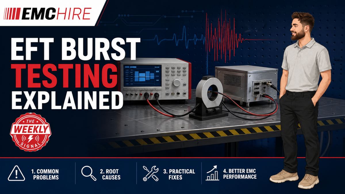
An EFT test can expose a reset mechanism in seconds, but a poorly bonded reference plane or misplaced cable can make the failure impossible to reproduce.
EFT burst testing examines whether electrical and electronic equipment continues to operate acceptably when subjected to repetitive, fast transients. These disturbances are associated with events such as relay contact operation, interruption of inductive loads and switching within power distribution systems. The test is severe because the pulses have fast edges, arrive in bursts and can couple into several circuits through different paths.
What EFT burst testing simulates
Electrical fast transient, usually abbreviated to EFT, is an immunity phenomenon rather than an emissions measurement. The applicable product or product-family standard may call up IEC 61000-4-4 as the basic test method and specify which ports are tested, the required test levels, application time, polarity and performance criteria.
The disturbance consists of repetitive fast pulses arranged into bursts. A single pulse may carry relatively little energy compared with a surge impulse, but the combination of a fast rise time, broad spectral content and repeated application can disturb digital logic, communications, analogue sensing and supervisory circuits. Common symptoms include processor resets, corrupted data, false input transitions, communication drop-outs and unintended actuator operation.
EFT must not be treated as a lower-energy version of surge testing. IEC 61000-4-4 addresses repetitive fast transients, while IEC 61000-4-5 addresses surge immunity associated with higher-energy events such as switching and lightning-related coupling. The generators, coupling arrangements, waveforms and failure mechanisms are different. A product that performs well during surge testing may still be vulnerable to EFT because its high-frequency current paths are poorly controlled.
The test equipment and coupling path
An EFT test system normally includes a calibrated transient generator, a coupling and decoupling network for relevant supply ports, and a capacitive coupling clamp where the method requires indirect application to signal, control or communication cables. A defined reference ground plane and compliant interconnection hardware are also part of the measurement system, not optional laboratory furniture.
For AC or DC power ports, the transient generator is typically connected through the appropriate coupling and decoupling network. This applies the disturbance to the selected conductors while restricting unwanted propagation towards auxiliary equipment or the external supply. The network must suit the port voltage, current, conductor arrangement and test method. Using an underrated or incompatible network presents both a technical and a safety problem.
A capacitive coupling clamp provides a controlled means of coupling the burst onto eligible non-mains cables without making a direct conductive connection. The cable is routed through the clamp in the prescribed configuration. The clamp is not a current-injection probe and is not interchangeable with a CDN used for IEC 61000-4-6 conducted RF immunity or a BCI probe used by applicable current-injection immunity methods.
EMC Hire can provide suitable transient and surge test equipment, including equipment for defined development and compliance test windows. Selection should be based on the latest applicable standard, required test level, port type, EUT supply rating and coupling method rather than generator voltage alone.
How IEC 61000-4-4 fits into a compliance programme
IEC 61000-4-4 defines a basic immunity test method. It does not, by itself, establish the complete compliance requirements for every product. A product standard may modify or select the test levels, ports, durations, operating conditions and performance criteria. Examples include standards covering industrial equipment, information technology equipment, laboratory equipment, household products and adjustable-speed power drive systems.
Before testing, the compliance engineer should identify the applicable legislation and product-specific or product-family standards. Check the latest active editions, amendments, port definitions, equipment configuration, cable requirements, test levels, polarities, application times and performance criteria. Customer specifications may impose additional tests, particularly in automotive, aerospace and defence programmes.
For CE or UKCA work, immunity results may contribute to the technical file, EMC risk assessment, mitigation evidence and Declaration of Conformity process where the selected route permits self-certification. Testing alone does not discharge every conformity obligation. The manufacturer or responsible economic operator remains responsible for determining the applicable legislation, standards, assessment route and documentation.
Further practical support for these decisions is available through EMC Hire's CE marking and EMC compliance services. Formal testing can provide a more defensible evidence trail than undocumented bench checks, but no individual test result guarantees regulatory acceptance or market access.
Building a representative EFT test setup
Repeatability starts with geometry. The EUT, transient generator, coupling network, clamp, cables and reference plane must be arranged as required by the applicable method. Cable length, excess cable treatment, separation from the plane and the position of auxiliary equipment all influence the high-frequency return path.
Bonding is equally significant. A long connection between the generator and reference plane adds inductance. During a fast transient, that impedance can raise the local voltage, change common-mode current flow and produce a result that does not represent the prescribed setup. Wide, short bonding connections generally provide lower high-frequency impedance than long wires, subject to the equipment manufacturer's instructions and the test method.
The EUT must operate in a mode that exercises vulnerable functions. Leaving an industrial controller idle may miss disturbances affecting analogue inputs, high-speed communications or switching outputs. Monitoring also needs enough bandwidth and logging resolution to capture brief effects. A reset that automatically recovers in 200 ms can disappear from view unless supply rails, communications, error logs and functional outputs are observed.
Test equipment used for meaningful compliance evidence should be within calibration and suitable for the required waveform and coupling arrangement. EMC Hire uses test equipment with calibration traceable through an appropriate ISO/IEC 17025 accredited calibration provider. Traceable calibration supports repeatability, confidence in recorded data and comparison between development testing and a later formal programme. It does not make the physical instrument or EMC Hire's facility ISO/IEC 17025 accredited.
Diagnosing an EFT failure
The first task is to establish the actual coupling path. Do not begin by adding suppression components at random. Determine whether the disturbance enters through the power port, a signal cable, chassis bonding, protective earth or a parasitic path involving auxiliary equipment.
Correlate the failure with polarity, conductor selection, port and EUT state. If a fault appears only when a communications cable is placed in the coupling clamp, investigate common-mode conversion, connector shield termination and the transceiver's protection network. If direct application to the supply causes a reset, examine power-distribution impedance, reset supervision, DC rail disturbance and high-frequency current flow between circuit ground and enclosure.
Near-field probing, current monitoring and oscilloscope measurements can help during pre-compliance debugging, provided probes and instruments are used safely and do not materially alter the circuit. A long oscilloscope earth lead can form a substantial pickup loop and show a dramatic waveform that is largely a measurement artefact. Differential or appropriately isolated measurement techniques may be required, with voltage ratings and transient safety considered before connection.
Accessible pre-compliance testing allows design teams to change filters, bonding, layout or firmware recovery behaviour while the prototype remains modifiable. The resulting data can improve confidence before formal testing and support self-certification where legally and technically appropriate. It should not be represented as automatic proof of compliance.
Typical scenario
Consider an illustrative industrial control unit with a mains input, Ethernet connection, analogue sensor cable and relay outputs. Its product standard calls up IEC 61000-4-4 with defined requirements for relevant power and signal ports.
The engineering team must select a transient generator with the necessary capability, a coupling network rated for the EUT supply and current, and a capacitive coupling clamp for applicable signal cables. They must also define representative operating modes. During testing, the controller could be switching its relay outputs, exchanging network traffic and processing changing sensor values while software records resets and communication errors.
Selecting a generator from voltage rating alone would be risky. The available coupling network may not support the EUT current, the clamp may not match the required method, or the system may lack suitable verification accessories. An informal setup on a wooden bench with uncontrolled cable routing could produce failures that disappear in the formal laboratory, or worse, miss a susceptibility that returns late in the programme.
Early investigation gives the team time to identify whether the weakness lies in connector bonding, power filtering, PCB return paths, protection components or firmware recovery. EMC Hire can support this work through equipment selection, conducted immunity testing support, on-site testing, pre-compliance engineering, test-facility access and formal compliance testing where appropriate.
Hiring the generator and coupling accessories for the development window avoids purchasing a specialist system for irregular use. It also reduces responsibility for long-term storage, servicing and calibration. For defence, automotive or aerospace development, EMC Hire can provide pre-compliance support, although contractual or programme requirements may require final testing by an appropriately accredited laboratory.
When to Hire EMC Equipment
EFT equipment is a strong candidate for hire when testing demand is concentrated around prototype releases or design-validation gates. A transient generator may otherwise remain unused for much of the year while continuing to incur calibration, maintenance, storage and asset-management costs.
Hiring also allows the equipment configuration to follow the project. One programme may require a coupling network suitable for a modest single-phase supply, while another needs a different port rating or coupling arrangement. Buying for the first programme can leave the business with equipment that is unsuitable for later products.
Short-term access is particularly useful when several projects converge, an internal system is away for calibration or a failure needs rapid reproduction at the design site. EMC Hire's range of transient generators and power-quality test equipment can support defined test windows without committing capital to a rarely used configuration.
The hire specification should state the required test method, product standard, EUT port voltage and current, conductor arrangement, test level, accessories and intended location. That information prevents a technically impressive generator arriving without the network or coupling hardware needed to perform the test.
Common EMC Testing Mistakes to Avoid
Treating the reference plane as optional
The plane provides a controlled high-frequency return path. Omitting it, using an unsuitable surface or making a poor bond changes the current distribution and undermines comparison with later laboratory results.
Routing cables for convenience
Cable height, length, separation and excess-cable arrangement affect capacitive and inductive coupling. Moving a cable between test runs can change the stress reaching the EUT, leaving the team unable to distinguish a genuine design improvement from a setup change.
Using the wrong coupling device
A capacitive coupling clamp, EFT coupling network, IEC 61000-4-6 CDN and BCI probe serve different methods and coupling paths. Substitution can apply an uncontrolled disturbance, damage connected equipment or create invalid evidence.
Testing an idle or unmonitored EUT
A powered unit is not necessarily a representative unit. If communications, analogue channels and outputs are inactive, susceptible circuits may never be exercised. Without time-correlated monitoring, short interruptions can also be missed.
Recording only pass or fail
Records should include equipment identification, calibration status, setup photographs, cable positions, ports tested, polarity, levels, application times, EUT modes, monitoring methods and observed behaviour. A bare pass statement is difficult to reproduce and provides weak evidence for a technical file or design review.
Applying the wrong performance criterion
A temporary degradation may be acceptable for one product function and unacceptable for another. Performance criteria must come from the applicable product requirements and risk assessment, not from a generic assumption that automatic recovery always constitutes a pass.
Frequently Asked Questions (FAQs)
Is EFT burst testing the same as surge testing?
No. EFT testing addresses repetitive fast transients under IEC 61000-4-4, while surge testing typically follows IEC 61000-4-5 and represents a different, generally higher-energy phenomenon. The generators, waveforms and coupling networks must match the selected method.
Does every cable require a coupling clamp test?
Not necessarily. Port applicability depends on the product standard, cable type, intended installation, cable length and other defined conditions. Check the latest requirements rather than applying the clamp indiscriminately.
Can EFT testing be performed at the design site?
Often, provided there is suitable space, a controlled reference plane, safe power arrangements, appropriate coupling equipment and a documented setup. On-site work can be effective for debugging because design engineers and diagnostic tools are immediately available.
What should be monitored during the test?
Monitor safety-related functions, communications, processor state, power rails, analogue accuracy, outputs, alarms and data integrity as applicable. The monitoring system must not introduce an unintended coupling path or mask the disturbance.
Can pre-compliance EFT results support CE marking?
Calibrated pre-compliance data may support engineering decisions and technical documentation, particularly under an appropriate self-certification route. It does not automatically prove conformity. The manufacturer must confirm applicable legislation, standards, test requirements and documentation obligations.
How should a team select a transient generator?
Start with the applicable product standard and IEC 61000-4-4 method requirements. Then consider test level, waveform capability, coupling network ratings, clamp requirements, verification arrangements, EUT supply characteristics, calibration status and operator safety.
Plan the test before the generator arrives
A useful EFT programme is built around the product ports, operating states, performance criteria and real coupling paths. Defining those details early avoids hiring the wrong accessories, repeating invalid tests or reaching formal compliance testing with an unexplained reset mechanism.
To discuss equipment hire, on-site testing, pre-compliance investigation, formal compliance testing or space at the EMC Hire test facility, contact the engineering team on +44 (0)1462 817111 or email sales@emchire.co.uk. Providing the product standard, port ratings and proposed test levels with the enquiry will help the team specify an appropriate test arrangement.
Disclaimer: Content is for informational purposes only and does not constitute formal engineering or regulatory advice. Always verify testing procedures against current official standards (e.g., ISO, MIL-STD, DEF STAN). EMC Hire Limited accepts no liability for outcomes resulting from the use of this information.