

Radiated emissions troubleshooting from a noisy display module
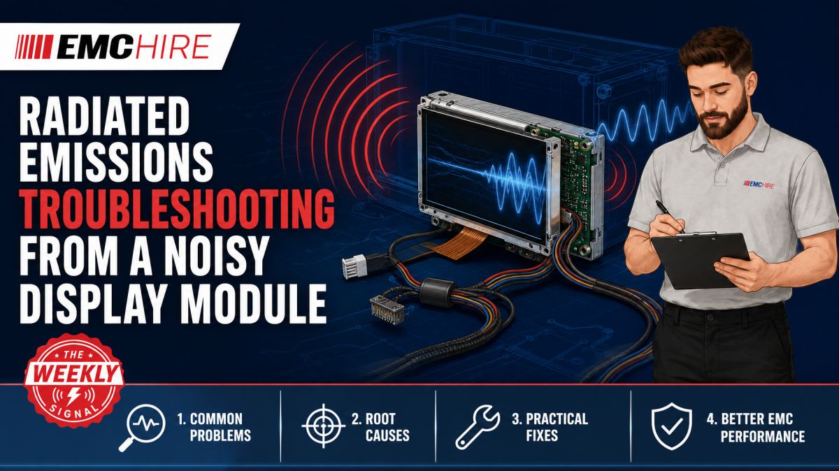
A display can pass every functional test yet turn its interface cable, power loom and enclosure seams into an efficient antenna.
This radiated emissions case study is an illustrative engineering scenario rather than a record of a named customer project. It shows how to distinguish noise generated inside a display module from emissions created by the host processor, interface timing, power conversion and cable coupling.
Why display subsystems create emission hotspots
Modern display assemblies combine several fast-switching circuits in a compact area. A typical subsystem may contain an LCD or OLED panel, timing controller, serial display interface, backlight driver, local DC-DC converters and a flexible printed cable. Individually, none may appear problematic. Together, they create multiple common-mode conversion paths.
The pixel clock is rarely the only frequency of interest. Data edges contain harmonic energy well above the fundamental clock, while spread-spectrum clocking, data encoding and frame timing can produce groups of spectral components rather than one clean line. A nominally low-frequency interface can therefore contribute to radiated emissions far into the measurement range.
Edge rate matters more than clock rate when considering harmonic content. Reducing a 50 MHz clock to 40 MHz will not necessarily solve the problem if the driver still switches in sub-nanosecond time. The spectral envelope is strongly influenced by rise and fall times, source impedance, transmission-line discontinuities and common-mode conversion.
Displays also create physically large current loops. A poorly defined return path through a flexible cable, connector or mechanical frame allows high-frequency current to find alternative routes through chassis metal, protective earth, peripheral cables or an operator-accessible I/O lead. Those structures can radiate more effectively than the display PCB itself.
Establishing whether the display is really the source
Correlation comes before modification. Begin by recording the frequencies, amplitudes, antenna polarisation, EUT orientation and operating mode associated with each emission hotspot. Radiated emissions commonly begin at 30 MHz, but the applicable lower and upper frequencies, detector requirements, test distance and limits depend on the product standard and the highest frequencies generated or used by the equipment.
For multimedia equipment, CISPR 32 may be relevant. Other products can fall under different product or product-family standards. The current published edition, product scope, port definitions, operating modes, measurement method and limits must be checked rather than inferred from a generic emissions setup.
A compliant receiver or suitably configured spectrum analyser can be used during development work, provided its frequency range, dynamic range and detector facilities are appropriate. Peak detection is useful for rapid searching. Final comparison may require CISPR quasi-peak or average detection according to the applicable standard. Resolution bandwidth must also follow the relevant frequency range and method. A convenient analyser setting is not automatically a defensible compliance setting.
Operate the EUT in controlled states:
- Display enabled with representative moving content.
- Display enabled with static content.
- Backlight at minimum, intermediate and maximum demand.
- Display interface active with the panel disconnected, where electrically safe and supported.
- Interface disabled while the rest of the product remains operational.
- Alternative refresh rates, colour depths or link rates that are valid user modes.
If an emission follows the interface enable state but not backlight level, the serial link or timing controller becomes the stronger suspect. Components that move with dimming demand may originate from a pulse-width-modulated backlight driver or its converter. A frequency that remains unchanged when the whole display subsystem is disabled probably belongs elsewhere.
Do not use an abnormal diagnostic mode as the only evidence. A blank panel may reduce processor activity, memory traffic and data transitions, producing an unrealistically favourable result. Formal testing should exercise representative worst-case operating modes defined through the applicable standard and product risk assessment.
Near-field probing and correlation
Near-field probes are diagnostic tools, not substitutes for the specified radiated emissions antenna measurement. Magnetic-field probes help locate high-frequency loop currents around inductors, connectors, flex tails and return-path discontinuities. Electric-field probes can reveal strong voltage-driven coupling near display edges, high-impedance nodes and unshielded conductors.
Probe orientation and distance must be controlled. Rotating a magnetic probe by 90 degrees can change the response substantially, while moving it a few millimetres may produce an apparently dramatic improvement. Photograph the probe position or use a simple non-conductive fixture when comparing modifications.
Search at frequencies already identified during the radiated scan. A large near-field indication at an unrelated frequency may be electrically interesting but irrelevant to the failed limit. Conversely, a modest local signal that correlates exactly with an external emissions peak may identify the more significant coupling path.
A current probe around an external cable provides another useful correlation measurement. If common-mode cable current rises at the same harmonics seen by the antenna, the cable is probably acting as part of the radiating structure. The reading is not directly interchangeable with field strength in dBµV/m, but it can show whether a proposed filter, bond or routing change is affecting the right mechanism.
Separating source, coupling path and antenna
Effective troubleshooting treats the problem as three linked elements. The display electronics generate RF energy, an impedance imbalance converts or couples that energy into common mode, and a cable or mechanical structure radiates it. Shielding only the source may fail if noise is already flowing on the interface cable outside the shielded region.
Interface return-path discontinuities
Differential display interfaces depend on closely controlled geometry and a continuous return structure. Connector pin assignments, flex transitions, reference-plane splits and long via stubs can disturb balance. Even when the receiver eye diagram remains acceptable, a small differential-to-common-mode conversion can create a radiated failure.
Inspect the entire route rather than the central section alone. A well-routed differential pair that crosses a plane void near the connector forces return current to spread around the discontinuity. The resulting loop area raises inductance and can excite the display cable or chassis.
Display frame and shield bonding
A metal display frame is not automatically an RF shield. If it is bonded through one long wire or narrow PCB trace, its impedance can be high at the troublesome harmonic. The frame may then float electrically and behave as a parasitic radiator.
Short, wide, low-inductance bonds at appropriate locations generally perform better than a long pigtail. Multiple bonding points can reduce seam length, although they must be assessed against safety, corrosion, ESD and low-frequency grounding requirements. Conductive fabric, spring fingers or gasketing can help, but only when mating surfaces and compression remain controlled through manufacture.
Power and backlight converter coupling
Display noise can leave through the power input rather than the video interface. Local converter ripple and switching edges may couple onto the host supply, then reach a longer wiring harness. A conducted emissions investigation can help identify this path on relevant power ports using an appropriate LISN and receiver configuration.
A LISN is used for conducted emissions measurement, not conducted immunity. EMC Hire provides information on conducted emissions systems and suitable line impedance stabilisation networks. The network type, current rating, voltage rating, earthing arrangement and standardised impedance must match the port and test method.
Typical scenario
Consider an illustrative industrial controller with a processor board, metal-backed display, internal display flex and an external communications cable. A preliminary radiated scan shows several narrow peaks that change when the display refresh rate is altered. Horizontal antenna polarisation produces the higher reading in one orientation, while a current probe shows corresponding RF current on the communications cable.
The engineering team first confirms the operating state and records a baseline in a repeatable setup. Disabling the backlight does little, but disabling the display link removes the principal harmonics. Near-field probing finds strong activity at the processor-side display connector and along one edge of the flex. The display frame itself is noisy near its single pigtail connection.
These observations suggest that the processor and interface are generating the energy, a return-path discontinuity is converting part of it into common mode, and the frame plus external cable are providing the radiating structures. Replacing the pigtail with a shorter, wider bond may reduce frame voltage. Improving connector ground distribution, adding an appropriate common-mode filtering component, controlling edge rate where signal integrity permits, and rerouting the flex away from enclosure apertures can then be evaluated one change at a time.
Component selection cannot be based solely on insertion-loss graphs. A common-mode choke must support the interface data rate, differential impedance and signal integrity requirements. Parasitic capacitance can reduce high-frequency attenuation, while poor PCB placement may allow noise to couple around the component. Manufacturer documentation and measured S-parameters should be reviewed at the frequencies of concern.
The updated configuration is rescanned at the original positions and operating modes. Only after confirming improvement in the accessible debugging setup should the product return to a formal programme. Early investigation reduces the chance of discovering that a moulding, flex cable or enclosure tool needs modification after design release.
EMC Hire can support this type of work through equipment hire, pre-compliance engineering, on-site measurements and access to an EMC test facility. Formal compliance testing may then provide evidence for the technical file, Declaration of Conformity, mitigation records and self-certification process where that route is applicable. The manufacturer remains responsible for identifying the legislation, standards, conformity assessment route and documentation requirements.
Choosing mitigation without creating another failure
Series resistance at the source can slow an edge and damp ringing, but excessive resistance may close the interface eye or breach timing margins. Ferrite material must be selected for impedance in the relevant frequency region and checked under DC bias. A part that looks effective at 100 MHz may offer little useful impedance at the actual hotspot.
Shielded cables also need correct termination. Connecting a cable shield through a long drain wire adds inductance and weakens high-frequency performance. A low-impedance circumferential or wide-area termination is generally more effective where the mechanical design allows it.
Keep each modification reversible during diagnosis. Changing shielding, firmware timing, filtering and bonding simultaneously may produce a passing scan without revealing why. That makes the result difficult to reproduce and exposes the project to regression when one change is removed during cost reduction.
When to Hire EMC Equipment
A radiated emissions investigation often needs equipment for days or weeks rather than throughout the product lifecycle. Hiring can provide an appropriate receiver or analyser, antennas, near-field probes, current probes, cables and supporting accessories for a defined development window without committing capital to a system that may not suit the next programme.
Short-term access is particularly useful when several prototypes arrive together, a formal test date is approaching or an intermittent display configuration needs extended debugging. It also avoids long-term storage, servicing and calibration overheads. RF interconnects deserve attention because damaged or poorly characterised cables can distort level comparisons. Suitable options are outlined in EMC Hire's RF and microwave cables and connectors information.
Equipment should be selected around the applicable frequency range, detector requirements, transducer factors, preamplifier headroom and expected signal environment. EMC Hire can assist with configuring a radiated emissions measurement system rather than supplying unrelated instruments that leave gaps in the measurement chain.
Where calibration affects the recorded result, EMC Hire uses test equipment with calibration traceable through an appropriate ISO/IEC 17025 accredited calibration provider. Suitable traceability supports repeatability, comparison between development and formal testing, and a stronger engineering evidence trail. It does not make a pre-compliance setup equivalent to an accredited test service.
Common EMC Testing Mistakes to Avoid
Moving cables between measurements
Display flexes and external leads can dominate radiation. If their position changes after every modification, a routing effect may be mistaken for a successful filter or shield. Mark positions, control bend radii and photograph the complete setup.
Testing a quiet but unrepresentative screen
A static image may produce fewer data transitions than video, animation or rapid menu updates. Using only the quiet state creates false confidence and weakens the evidence that representative operating modes were assessed.
Applying the wrong detector or bandwidth
Fast peak scans are useful for diagnosis, but they do not automatically establish compliance against quasi-peak or average limits. Incorrect receiver bandwidth changes measured noise and can invalidate comparison with the applicable limit.
Assuming the strongest near-field point is the radiator
A probe may identify the source but not the antenna. Reworking the display controller can consume days when the dominant problem is common-mode current on a cable caused by poor return continuity.
Ignoring ambient signals
Broadcast and mobile radio signals can resemble EUT emissions. Switching the EUT off, changing operating states and checking frequency correlation helps separate ambient activity from product-generated signals.
Recording only the final plot
Without cable positions, firmware version, screen content, antenna polarisation, test distance, EUT orientation and accessory configuration, another engineer may be unable to reproduce the result. That creates a weak compliance evidence trail even when the final trace looks acceptable.
Frequently Asked Questions (FAQs)
Can display harmonics be predicted from the pixel clock?
The clock provides useful starting frequencies, but edge rate, encoding, lane activity, converter clocks and common-mode conversion also shape the spectrum. Measure the actual subsystem in representative modes rather than relying only on integer harmonic calculations.
Should shielding be fitted before trying filters?
Not automatically. First identify the source and coupling path. Shielding can be ineffective if cable currents cross the shield boundary, while filtering may fail when frame bonding is the dominant problem.
Can a spectrum analyser replace an EMI receiver?
It can be effective for pre-compliance diagnosis if its performance and settings are suitable. Formal measurements may require compliant detector behaviour, bandwidths and measurement procedures that must be confirmed against the applicable standard.
Does a lower near-field reading prove lower radiated emissions?
No. It indicates a local change. Verification requires repeating the radiated measurement with controlled antenna position, distance, polarisation and EUT configuration.
When should conducted emissions be investigated?
Investigate when display or backlight noise appears on a relevant power lead or when cable-current measurements suggest the supply harness is carrying RF. Use a suitable LISN only where the applicable conducted emissions method calls for it.
Which standard applies to a display-based product?
That depends on the product function, intended environment, ports and regulatory route. A basic IEC test method is not a product emissions limit standard. Confirm the latest active edition of the relevant product or product-family standard, including test levels, frequency ranges, configurations, limits and documentation requirements.
From diagnosis to defensible evidence
A good display investigation ends with more than a cleaner trace. It establishes which operating modes were assessed, why the mitigation works, how the production configuration will preserve it and whether the revised product is ready for formal testing.
For help selecting equipment, arranging on-site testing, undertaking pre-compliance work or discussing formal compliance testing, contact the EMC Hire engineering team on +44 (0)1462 817111 or email sales@emchire.co.uk. Test facility space can also be booked for structured investigation before the design enters its final compliance programme.
Disclaimer: Content is for informational purposes only and does not constitute formal engineering or regulatory advice. Always verify testing procedures against current official standards (e.g., ISO, MIL-STD, DEF STAN). EMC Hire Limited accepts no liability for outcomes resulting from the use of this information.