

How to write an EMC lessons-learned review
An EMC failure report tells you what failed. A useful EMC lessons-learned review explains why the project allowed the failure to reach the test laboratory.
That distinction matters. Changing a filter, gasket or PCB layout may fix the product in front of you, but it does not prevent the next engineering team from repeating the same sequence of assumptions, late decisions and poorly controlled tests.
What an EMC lessons-learned review should achieve
An EMC lessons learned process should convert evidence from a test campaign into reusable engineering decisions. It is not a blame exercise, a condensed test report or a collection of opinions about what went wrong.
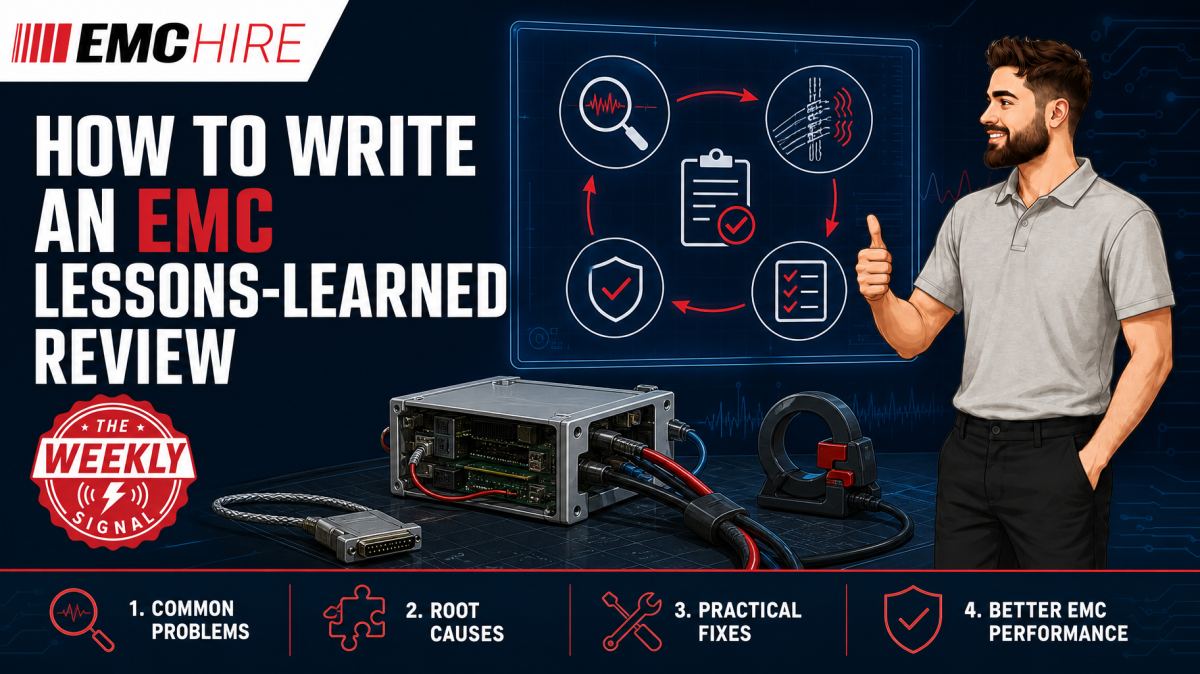
The review should establish four things:
- What was observed, under which controlled test conditions.
- Which coupling mechanism or design feature produced the result.
- What fix was applied and how its effectiveness was verified.
- Which process improvement will prevent or expose the same issue earlier.
The last point is frequently missed. If the only recorded action is to fit a larger common-mode choke, the organisation has documented a product modification rather than a lesson. A stronger action might require cable common-mode current measurements during prototype integration, or mandate review of power-port filtering before enclosure tooling is released.
A lessons-learned review also needs to distinguish evidence from inference. A repeatable emissions peak that disappears when an interface cable is removed is evidence that the cable participates in the radiating structure. It does not, by itself, prove whether the driving mechanism is poor PCB return continuity, connector bonding, cable shielding or common-mode conversion elsewhere.
Start with a controlled campaign record
Root-cause analysis becomes unreliable when the underlying test configuration cannot be reconstructed. Before discussing fixes, gather the test plan, equipment records, photographs, plots, software versions, EUT operating modes and modification log.
The baseline record should identify the applicable product or product-family standard, the test method called up by that standard, the EUT configuration and the performance criteria used for immunity testing. Check the latest active editions and confirm product scope, ports, test levels, frequency ranges, limits, operating modes and documentation requirements. Customer or contractual plans may add conditions that are not apparent from the published product standard.
For emissions work, record receiver settings and detector types rather than merely attaching screenshots. Peak, quasi-peak and average results are not interchangeable. Likewise, a conducted emissions result obtained using a LISN on a relevant power port cannot be compared directly with a current-probe diagnostic trace unless the differing quantities and measurement paths are understood.
Immunity records need equal discipline. A conducted RF immunity test using a CDN under a method such as IEC 61000-4-6 is not equivalent to a BCI test used by an applicable automotive, military or aerospace procedure. The coupling device, calibration method, injection quantity and cable configuration affect what is being stressed.
Build an event timeline, not a retrospective story
Teams naturally reconstruct events around the fix that eventually worked. This creates hindsight bias. Build a dated or sequential timeline from contemporaneous records instead:
- Initial configuration and baseline result.
- Each diagnostic change, including unsuccessful changes.
- Observed effect on the relevant failure signature.
- Restoration checks confirming that the effect was repeatable.
- Final corrective design and verification configuration.
Record failed experiments. They narrow the possible coupling paths and can stop another team spending a day repeating the same investigation. A ferrite that produced no measurable change is useful evidence if its material, position, number of turns and test configuration are known. The statement “ferrite did not work” is not.
Separate symptom, root cause and fix
These three terms are routinely collapsed into one.
A symptom is the observed non-conformity or performance degradation. Examples include a conducted disturbance exceeding a limit at a defined frequency, a radiated emissions peak associated with a clock harmonic, or an unintended reset during an immunity test.
The root cause describes the physical mechanism and the design or process decision that permitted it. For example, an immunity reset might result from RF current coupling onto an external cable, converting to differential voltage at a poorly balanced interface and entering a reset line through inadequate filtering. “Insufficient immunity” is not a root cause.
The fix is the verified corrective action. It may involve filtering, shielding, bonding, component selection, PCB return-path control, firmware behaviour or a combination of measures. Avoid claiming causation merely because one modification improved the result. Repeat the change, remove it where practical, and check whether the original signature returns.
Use two levels of root-cause analysis
Technical root cause asks why the EUT behaved as it did. Process root cause asks why the issue was not found sooner.
Suppose a cable shield was connected to circuit reference through a long PCB trace rather than bonded to the enclosure at the connector entry. The technical mechanism may be shield current flowing through internal circuitry and generating common-mode voltage. The process root cause could be an incomplete connector specification, lack of an EMC review at mechanical design release, or uncertainty over ownership between PCB and enclosure teams.
Both levels deserve corrective action. Solving only the technical mechanism leaves the development process unchanged.
Typical scenario
Consider an illustrative, not customer-specific, example. A networked industrial controller enters pre-compliance testing late in development. Conducted emissions on its mains power port are investigated using an appropriate LISN and measuring receiver. Radiated emissions are assessed separately with a suitable antenna and controlled measurement geometry.
The team finds a narrowband radiated issue that changes significantly with Ethernet cable placement. Initial discussion focuses on adding ferrites. Before selecting a fix, the engineers compare EUT modes, monitor cable common-mode current, inspect connector bonding and check whether the enclosure panels maintain RF continuity.
The investigation indicates that the cable is acting as a radiating path, driven by common-mode conversion near the interface. A revised connector-bonding arrangement and local layout change reduce the diagnostic signature. The configuration is then restored and reapplied to establish repeatability before a representative unit is retested.
A weak lessons review would say, “Add improved Ethernet filtering.” A useful review would record the observed frequencies, operating mode, cable construction and position, measurement uncertainty considerations, diagnostic sequence, coupling model, unsuccessful modifications and verification evidence. It would also add a design-gate check covering shield termination and connector-to-enclosure bonding.
Early access to a controlled setup makes that investigation less expensive. EMC Hire can support equipment selection, equipment hire, pre-compliance engineering, on-site testing, access to an EMC test facility and formal compliance testing where appropriate. Its EMC test capabilities can be considered when planning the route from prototype diagnosis to documented testing.
Pre-compliance data does not automatically prove compliance, but calibrated engineering measurements can reduce uncertainty before a formal programme. EMC Hire uses test equipment with calibration traceable through an appropriate ISO/IEC 17025 accredited calibration provider. Suitable, traceable calibration supports repeatability, comparison between development and formal tests, and a stronger evidence trail.
Turn findings into owned process improvement
Every agreed action needs an owner, due date, affected process and closure criterion. “Improve EMC awareness” cannot be audited. “Add cable shield termination review to the schematic and mechanical design checklist before layout release” can.
Process changes may affect design rules, component libraries, supplier specifications, test plans, prototype availability or training. Assign the action to the person who controls that process, not automatically to the engineer who diagnosed the fault.
Closure should require evidence. That might be an updated checklist, an approved PCB rule, a revised interface specification or a completed diagnostic test on the next prototype. Review the action again after the following project. Some changes look sensible in a meeting but create unnecessary constraints or are quietly bypassed under schedule pressure.
Capture the information in a searchable engineering repository using consistent terms for the affected port, phenomenon, coupling path and corrective action. Link the review to the test report and technical file, while retaining configuration-controlled source records.
Robust evidence can support EMC risk assessments, gap analysis of the intended RF environment, mitigation records, Declarations of Conformity and self-certification processes where applicable. Testing alone does not complete every conformity obligation. The manufacturer or responsible economic operator remains responsible for confirming applicable legislation, standards, conformity assessment routes and documentation.
When to Hire EMC Equipment
Hiring is often rational when the investigation requires a particular receiver, LISN, current probe, antenna, ESD simulator or immunity generator for a defined window rather than continuous use. It avoids committing capital to equipment that may not suit the next product standard or frequency range.
Short-term hire can also expand internal capability during prototype peaks, regression campaigns or urgent fault investigations. Ownership carries storage, maintenance, servicing and calibration overheads, as well as the risk that infrequently used equipment becomes obsolete or falls outside calibration before the next programme.
Selection still needs engineering scrutiny. The instrument bandwidth, dynamic range, accessories, coupling device and calibration status must fit the intended method. Hiring an analyser without the correct LISN, limiter or transducer does not create a valid conducted emissions setup.
Where a team lacks a suitable environment or experienced operators, booking facility time or arranging on-site support may produce more defensible data than assembling an improvised setup. EMC Hire can help determine whether rental, pre-compliance work, formal testing or a combined approach best matches the project stage. The company’s EMC test guides provide further practical planning information.
Common EMC Testing Mistakes to Avoid
Changing several variables together
Adding a ferrite, rerouting a cable and changing firmware in one step may produce a pass, but it destroys causal information. Apply one controlled change at a time unless safety or schedule constraints prevent it, then document the limitation.
Failing to preserve cable geometry
Cable position, length, termination and proximity to the reference plane can materially change coupling. Photographs should include scale and fixed reference points. An unexplained cable movement can make a promising fix appear effective or hide a real regression.
Using unrepresentative operating modes
An idle EUT may suppress switching activity, network traffic or actuator loads that dominate emissions. Immunity monitoring can also miss intermittent degradation if the exercised function is too simple. Record software, traffic, loads and duty cycles precisely.
Confusing diagnostic data with compliance evidence
Near-field probes and current probes are powerful localisation tools, but their traces do not replace the measurement method and limits required by the applicable standard. Treat relative diagnostic results as such.
Losing the failed baseline
Once hardware has been reworked, the original configuration may be impossible to recover. Retain an unmodified unit where feasible, photograph modifications and keep component values and assembly instructions under revision control.
Writing conclusions beyond the evidence
A single improved scan does not establish production robustness. Check repeatability, operating modes, unit variation and whether the modification introduces another emissions or immunity weakness. Poorly qualified conclusions create false confidence and an unsuitable compliance evidence trail.
Frequently Asked Questions (FAQs)
Should the lessons review replace the EMC test report?
No. The test report records the method, configuration and results. The lessons review interprets the project experience, identifies root causes and assigns process improvements. Link them without altering the controlled report.
Who should attend the review?
Include the test engineer, relevant hardware and mechanical designers, firmware representatives, the compliance lead and the manager able to own process changes. Procurement or manufacturing input may be needed where shielding, cabling or assembly controls contributed.
When should the review take place?
Hold a short technical capture immediately after testing, while configurations are still available. Conduct the wider process review once root-cause and verification evidence has matured. Waiting until project closure usually loses detail.
How much confidence is needed before naming a root cause?
State the confidence level and evidence. Reversible modifications, repeated measurements and results consistent with a physical coupling model provide stronger support than one successful rework. Record unresolved alternatives rather than forcing certainty.
Can pre-compliance findings support a technical file?
They can contribute calibrated engineering evidence, risk assessment and mitigation records, but their relevance depends on the applicable conformity route and test quality. They should not be presented automatically as formal proof of compliance.
Does the same process apply to defence, automotive and aerospace work?
The evidence discipline does, but test methods, configuration control and contractual approval routes differ. EMC Hire can provide pre-compliance support in these sectors, while final testing may require an appropriately accredited laboratory depending on programme or contractual requirements. Related RF risk considerations are discussed in RF safety and compatibility engineering.
Plan the next campaign around the evidence
A good review ends with changes to the next project plan: earlier prototype access, defined diagnostic measurements, clearer configuration control and a realistic formal test window. That is where EMC lessons learned become measurable process improvement rather than archived meeting notes.
To discuss equipment selection, request a hire quotation, arrange on-site testing, book the EMC Hire test facility or plan pre-compliance and formal compliance work, contact the EMC Hire engineering team on +44 (0)1462 817111 or email sales@emchire.co.uk.
Disclaimer: Content is for informational purposes only and does not constitute formal engineering or regulatory advice. Always verify testing procedures against current official standards (e.g., ISO, MIL-STD, DEF STAN). EMC Hire Limited accepts no liability for outcomes resulting from the use of this information.