

How to choose EMC equipment by frequency range
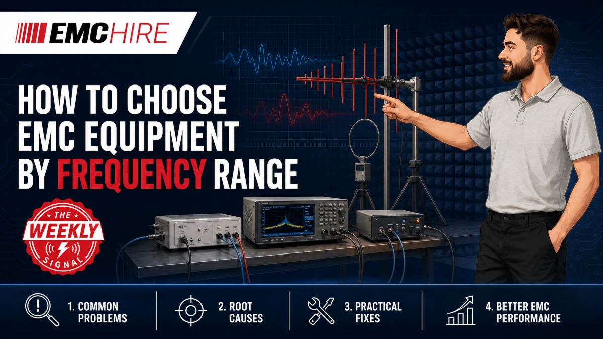
An instrument covering the stated frequency is not necessarily suitable for the test. Transducer factors, power output, detector behaviour and coupling method often expose the mismatch.
Frequency range is a starting point for EMC equipment selection, not the complete specification. Test engineers must also consider whether the task is emissions or immunity, conducted or radiated, diagnostic or formal, and whether the complete measurement chain remains characterised across the required band.
Start with the applicable requirement, not the equipment catalogue
Define the test from the applicable product or product-family standard before selecting hardware. A generic frequency specification cannot establish port applicability, limits, test levels, performance criteria, operating modes or the required coupling arrangement.
Conducted emissions measurements on relevant power ports are commonly made from 150 kHz to 30 MHz, using a suitable LISN and receiver, but that range is not universal. CISPR 11, CISPR 32 and other product-family standards have different scopes and configurations. Radiated emissions commonly begin at 30 MHz, while the upper frequency depends on the product, applicable standard and highest internal frequency.
Immunity requires a different equipment chain. IEC 61000-4-3 describes a basic radiated RF immunity method, while IEC 61000-4-6 addresses conducted RF immunity. Product standards determine whether those methods apply and specify the relevant levels, ranges and performance criteria. The IEC standards development information provides useful context, but engineers must check the latest active edition of every applicable standard and any contractual test plan.
Map the EMC frequency range to the whole signal chain
The usable range is set by the narrowest or least capable component. For an emissions measurement, that chain may include a LISN or antenna, cable, attenuator, pre-amplifier and measuring receiver. For immunity, it may include a signal generator, power amplifier, directional coupler, power meter, cable, coupling device or antenna.
A label such as 10 kHz to 1 GHz only shows nominal coverage. It says nothing about antenna factor, gain flatness, compression, mismatch tolerance, receiver dynamic range, cable loss or available field strength.
Receivers and analysers for emissions work
An EMC receiver should cover the required frequency range and provide the detectors, bandwidths and measurement functions called up by the relevant standard. Peak detection is useful for rapid scanning, but final assessment may require quasi-peak or average detection. Detector choice cannot be inferred from frequency alone.
Resolution bandwidth must also follow the applicable method and band. Applying one bandwidth across an entire sweep can change measured amplitudes, mask narrowband disturbances or exaggerate broadband noise. A general-purpose spectrum analyser can be highly effective for debugging, provided its limitations are understood, but it should not automatically be treated as equivalent to a standards-compliant receiver.
Dynamic range matters. Strong out-of-band signals can overload the input or pre-amplifier without producing an obvious overload warning. Attenuation, preselection and pre-amplification should be chosen as a system. Otherwise, the plot may contain internally generated intermodulation products rather than emissions from the equipment under test, or EUT.
Antennas must suit the band and the test direction
No single antenna offers equally good performance from low MHz frequencies into several GHz. Physical size, element geometry, balance and feed arrangement all affect usable bandwidth and sensitivity.
Biconical antennas are commonly used over lower radiated emissions bands, while log-periodic and horn antennas cover progressively higher frequencies. The exact crossover points depend on the antenna model, chamber or site arrangement and applicable method. Review the manufacturer's calibrated antenna-factor data rather than choosing solely from the headline range.
For radiated immunity, power handling, gain and voltage standing-wave ratio become prominent. An antenna suitable for receiving weak emissions may not tolerate the forward power needed to generate the required V/m field. Conversely, a high-power transmitting antenna may provide inconvenient sensitivity or geometry for low-level emissions measurements.
EMC Hire provides access to EMC antennas and near-field probes for defined test and diagnostic bands. Selection should include connector type, cable loss, polarisation, test distance, field uniformity requirements and physical space.
RF amplifiers require more than nominal bandwidth
For radiated or conducted immunity, amplifier selection begins with frequency coverage but is usually determined by power at the worst point in the band. Gain roll-off, cable loss, antenna efficiency, coupling-device insertion loss and load mismatch reduce the power reaching the test setup.
Rated saturated power is not the same as clean, usable test power. Operating too close to compression distorts modulation, changes harmonic content and can make level control unstable. Allowing sensible headroom improves repeatability and protects the amplifier when the load presents a poor match.
Lower-frequency applications can be supported by appropriate RF amplifiers covering bands up to 1 GHz. Higher-frequency or low-noise measurement applications may instead call for suitable RF amplifiers and pre-amplifiers. A pre-amplifier used to improve receiver sensitivity is not interchangeable with a power amplifier used to generate an immunity test level.
Probes are diagnostic tools, not automatic compliance transducers
Near-field probes help locate noisy converters, clock lines, cable exits and return-current discontinuities. Magnetic probes respond primarily to local magnetic fields and current loops. Electric-field probes are more responsive to voltage-driven structures and fringing fields.
The probe's physical size affects spatial resolution and sensitivity. A large loop can detect a weak source but may combine several nearby fields, hiding the actual origin. A very small probe improves localisation but may require a low-noise pre-amplifier and careful control of probe orientation.
Near-field amplitude is strongly dependent on spacing and angle. A few millimetres of movement can change the indication considerably, so probe results should normally be treated as comparative diagnostic data rather than direct predictions of far-field compliance. EMC Hire's near-field probe options can support repeatable board-level investigation when matched to the frequency of interest.
Frequency coverage for conducted test equipment
LISNs are used for conducted emissions measurements on relevant power ports. Selection depends on the required impedance network, current rating, voltage rating, phase arrangement, connector system and frequency range. Using a network with inadequate current capability creates a safety and measurement risk. Choosing the wrong impedance characteristic makes the receiver voltage unrepresentative of the specified method.
Conducted RF immunity under IEC 61000-4-6 commonly uses a CDN where the relevant port and method permit it. A CDN controls common-mode coupling and impedance more predictably than an improvised injection arrangement. Bulk current injection probes belong to applicable automotive, military, aerospace and product-specific current-injection procedures. A BCI probe and CDN should not be substituted for one another simply because their frequency ranges overlap.
Current monitoring probes need adequate transfer-impedance characterisation, aperture size and current handling. Clamp position and cable geometry must be controlled. Moving the probe along a harness changes the standing-wave and common-mode current distribution, so an undocumented position can prevent later reproduction of the result.
Calibration, correction data and measurement uncertainty
Calibration status must cover the period of use, but the certificate date alone is insufficient. Confirm that calibration covers the range, functions and accessories being used. Antenna factors, probe transfer impedance, LISN impedance, amplifier gain and cable loss may all contribute to the corrected result.
EMC Hire uses test equipment with calibration traceable through an appropriate ISO/IEC 17025 accredited calibration provider. Suitable traceability supports measurement accuracy, repeatability and comparison between development and formal testing. It also produces stronger engineering evidence for technical files, internal reviews and regulatory scrutiny. This wording relates to the calibration provider or activity, not accreditation of the physical instrument or EMC Hire's laboratory.
Correction data should be controlled by serial number. Applying the factor for another antenna or cable can shift an otherwise careful measurement. For immunity systems, forward power alone does not prove field strength or injected level. The setup must be calibrated or levelled using the method required by the applicable test procedure.
Typical scenario
Consider an illustrative industrial controller containing a switch-mode supply, Ethernet interface and processor clocking above 100 MHz. The team needs conducted emissions investigation, radiated emissions debugging and confidence that later immunity work can cover the product-standard requirements.
A sensible initial setup might combine a correctly rated LISN and receiver for relevant power-port emissions, near-field probes for board diagnosis, and antennas covering the required radiated bands. A low-noise pre-amplifier may improve sensitivity at higher frequencies, but only after checking that strong ambient signals will not drive it into compression.
For immunity, the engineers must separately select signal generation, power amplification and the specified coupling method. Buying an amplifier because its upper frequency is sufficient could still leave too little linear output at the antenna or CDN after system losses. Early power-budget calculations and accessible pre-compliance measurements expose that problem before a formal test slot is booked.
Hiring allows the team to assemble the correct chain for a defined window without committing capital to equipment that may not suit the next programme. EMC Hire can support equipment selection, test setup, pre-compliance engineering, on-site work and access to test facilities. Formal compliance testing may also support technical documentation, Declarations of Conformity and a defensible evidence trail where the applicable conformity route permits self-certification. The manufacturer remains responsible for identifying the legislation, standards and documentation requirements.
When to Hire EMC Equipment
Hiring is particularly effective when the required EMC frequency range changes between projects. One programme may stop at 1 GHz, while another needs higher-frequency antennas, receivers and cables. Ownership then ties up capital in equipment that spends long periods unused while still requiring storage, servicing and calibration.
Rental also covers short project peaks. Extra receivers, probes or amplifiers can expand an internal laboratory without setting its permanent capacity around an exceptional workload. It reduces the risk of purchasing an instrument whose bandwidth is adequate but whose detectors, power, connectors or calibrated functions are unsuitable.
For irregular testing, hire costs can be aligned with a prototype build, investigation period or booked test window. Engineering support with chain selection is valuable here because one missing adaptor, underrated attenuator or unsuitable cable can stop the work despite every major instrument appearing correct on paper.
Common EMC Testing Mistakes to Avoid
Selecting solely by headline frequency range
Nominal coverage hides gain roll-off, receiver noise floor, antenna-factor variation and amplifier compression. The result may be poor sensitivity during emissions work or inadequate test level during immunity testing.
Using uncontrolled cable layouts
Cable position changes common-mode coupling and antenna behaviour. If routing, height and termination are not documented, repeated measurements can differ enough to send debugging in the wrong direction.
Ignoring losses above the instrument connector
Long coaxial cables, adaptors, attenuators and coupling devices all introduce frequency-dependent loss. Failure to include those losses understates emissions after correction or overstates the level delivered during immunity testing.
Applying the wrong detector or bandwidth
A fast peak scan is not automatically the final compliance measurement. Incorrect receiver settings can produce a false failure, false confidence or evidence that cannot be reconciled with later formal testing.
Treating probe readings as absolute compliance results
Near-field probes are highly sensitive to spacing and orientation. Without a fixture or recorded method, before-and-after readings may reflect hand position rather than a design improvement.
Testing an unrepresentative operating mode
An EUT placed in an idle or convenient mode may not exercise its fastest interfaces, heaviest loads or periodic transmitters. Passing that configuration says little about the worst-case mode required by the test plan.
Frequently Asked Questions (FAQs)
Should every item cover the entire EMC frequency range?
No. Equipment may be split into overlapping bands, provided each chain is suitable and characterised. Pay close attention to crossover frequencies, where neither antenna or amplifier may perform as well as its headline specification suggests.
Can a spectrum analyser replace an EMC receiver?
It can be effective for pre-compliance debugging if it has suitable frequency coverage, bandwidths, dynamic range and detector capability. Formal measurements may require receiver functions and procedures defined by the applicable standard, so equivalence should not be assumed.
How much amplifier headroom should be allowed?
There is no universal margin. Calculate the requirement from the target level, transducer performance, cable and coupling losses, modulation, field-uniformity result and worst-band mismatch. Confirm linear operation using manufacturer data and measured system behaviour.
Can near-field probes predict a radiated emissions failure?
They can identify frequencies and likely source regions, but do not directly reproduce the far-field coupling path. Enclosure seams, external cables and chassis currents may dominate the formal result even when the board-level source appears modest.
Does calibrated pre-compliance equipment prove compliance?
No. It provides stronger, repeatable engineering data and can reduce late-stage redesign risk, but compliance depends on the applicable requirements, representative configuration and correct formal procedure. Some defence, automotive and aerospace programmes may require final testing by an appropriately accredited laboratory.
Plan the equipment chain before booking the test window
Send EMC Hire the applicable standard or test plan, required frequency bands, EUT power details, interfaces, intended operating modes and whether the work concerns emissions, immunity or diagnosis. The engineering team can then help identify suitable antennas, amplifiers, probes, receivers and coupling equipment.
To request an equipment hire quotation, arrange on-site testing, discuss formal compliance or pre-compliance support, or book space at the EMC Hire test facility, call +44 (0)1462 817111 or email sales@emchire.co.uk.
Disclaimer: Content is for informational purposes only and does not constitute formal engineering or regulatory advice. Always verify testing procedures against current official standards (e.g., ISO, MIL-STD, DEF STAN). EMC Hire Limited accepts no liability for outcomes resulting from the use of this information.