

How to diagnose emissions from cable assemblies
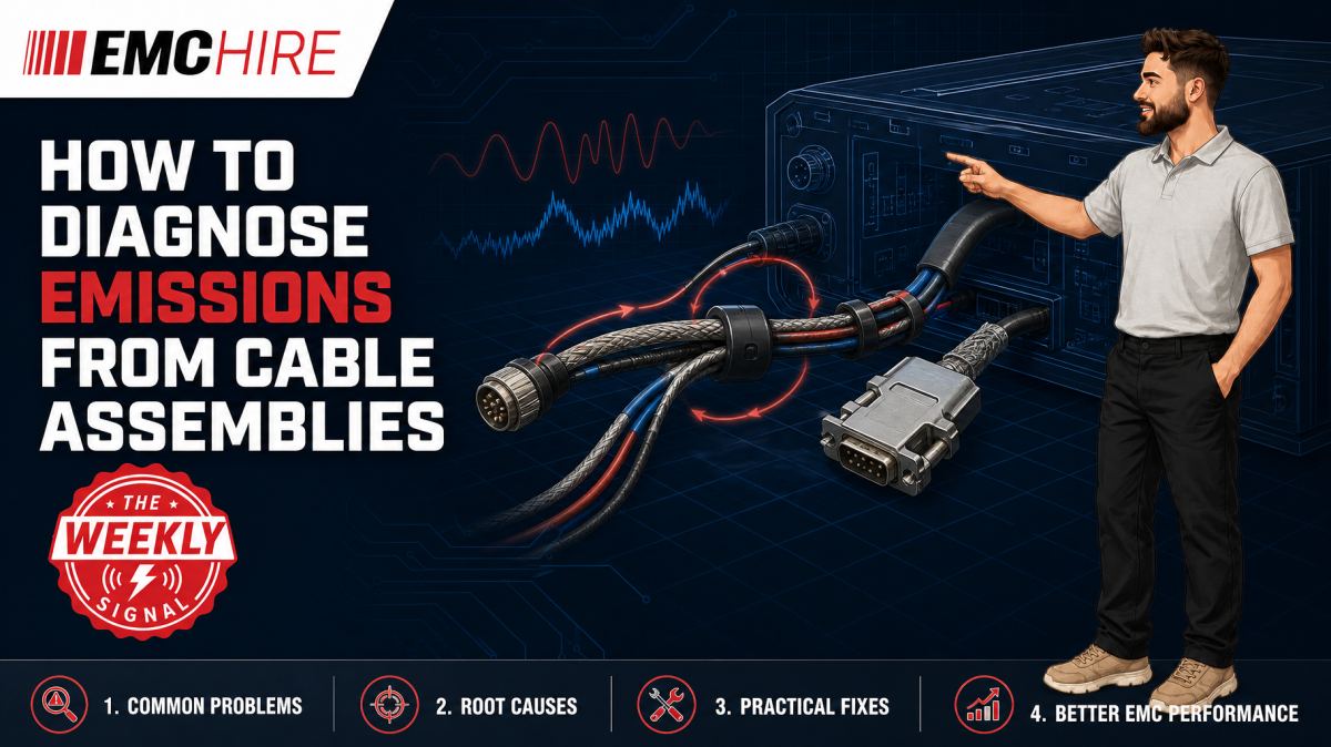
A cable does not need to carry an intentional RF signal to become an effective antenna. A few microamps of common-mode current on a long harness can dominate the radiated emissions result.
Diagnosing cable assembly emissions therefore starts with current paths, not with indiscriminate ferrite fitting. The objective is to identify where RF energy is generated, how it couples onto the assembly and why the intended return path is failing.
Why cable assemblies dominate emissions
Internal PCB traces are electrically short at lower frequencies and often radiate poorly by themselves. Attach a one-metre cable and the geometry changes. The cable may become a substantial fraction of a wavelength, while its connection to the enclosure, protective earth, remote equipment and nearby structures creates a much larger radiating system.
Differential-mode current flows out on one conductor and returns on another. If the conductor geometry is controlled and the loop area is small, the associated fields tend to cancel with distance. Common-mode current flows in the same direction on multiple conductors, with the return path formed through chassis, earth, stray capacitance or another cable. There is little field cancellation. This is why a small common-mode component can produce more radiation than a much larger differential signal.
The conversion is rarely mysterious. Typical mechanisms include imbalance in driver and receiver impedances, parasitic capacitance from switching nodes to chassis, discontinuities in reference planes, pigtail shield terminations, asymmetric connector pinning and current returning through an unintended mechanical structure.
Frequency points towards physical dimensions
A narrow emission at a clock harmonic suggests a deterministic source. A broad comb may indicate a switch-mode converter, fast digital interface or motor drive. The frequency tells you where to look, but not automatically which cable is radiating.
Relate each suspect frequency to cable length, enclosure dimensions and source edge rate. A cable can radiate below its textbook resonant frequency because real installations include loading, bends, dielectric materials and capacitive coupling to the reference plane. Treat simple wavelength calculations as diagnostic clues rather than pass or fail rules.
Changing cable length is a powerful experiment. If an emission peak shifts or changes substantially when the harness length or routing changes, the assembly is part of the resonant structure. If the spectral frequency remains fixed but amplitude changes, the source is probably stable while radiation efficiency or common-mode coupling has changed.
A systematic diagnostic method
Preserve the failing configuration
Start by recording the EUT operating mode, cable type, length, connector orientation, routing, support height, peripheral equipment and bonding arrangement. Photograph both ends of every cable. A result obtained with an undocumented harness position cannot be reproduced reliably, particularly near a limit where modest geometric changes can alter antenna coupling.
Use the operating mode that maximises representative cable activity and source switching. Artificial diagnostic modes are useful, but they should not replace realistic worst-case operation. A quiet software state can conceal the emission mechanism and create false confidence before formal testing.
Measure common-mode current directly
An RF current probe around the complete cable or harness is one of the most useful diagnostic tools. Passing all signal and return conductors through the aperture causes balanced differential currents to cancel substantially, leaving the net common-mode component. The probe output can be observed with a spectrum analyser or measuring receiver within the calibrated and characterised range of the probe and instrument.
Do not place only one conductor through the probe unless conductor current is deliberately being measured. That configuration includes differential current and can lead the investigation towards the wrong mechanism. Probe position also matters. Sweep along an accessible cable and record distance from the connector. Standing-wave behaviour can produce current maxima and minima, so one convenient location may not represent the assembly.
Convert probe voltage to current only using the applicable transfer impedance data and a measurement chain that accounts for cable loss, attenuation and instrument impedance. Manufacturer documentation should be checked for aperture constraints, frequency range, power limits and calibration conditions. A relative scan is useful for debugging, but uncorrected analyser amplitude should not be presented as a traceable current measurement.
Correlate current with radiated emissions
Compare current-probe peaks with the radiated spectrum from an antenna measurement. Matching frequencies strongly support a cable radiation hypothesis, although amplitude correlation may not be linear because antenna coupling depends on geometry and polarisation.
For structured investigations, use a controlled setup with fixed antenna distance, EUT orientation and cable routing. EMC Hire's radiated emissions measurement systems can support development measurements where repeatable spectral comparison is needed. Formal measurements must follow the applicable product or product-family standard, including its test site, distance, detector, bandwidth, EUT arrangement and cable requirements.
Use controlled perturbations
Change one parameter at a time. Clamp-on ferrite, temporary chassis bonding, revised shield termination or altered cable routing can reveal the coupling path, but multiple simultaneous changes destroy diagnostic value.
- Place a suitable ferrite around the whole cable near the EUT connector to impede common-mode current.
- Temporarily improve shield bonding with a short, wide conductive connection.
- Move the harness relative to seams, apertures and switching nodes while preserving the documented test geometry.
- Disconnect non-required peripherals individually where the operating state permits.
- Reduce source activity or edge rate through a controlled firmware or hardware change.
If a ferrite close to the connector produces a strong reduction, common-mode current is implicated. It does not prove that the ferrite is the right production fix. Core material, aperture, turns, DC bias, temperature and cable current all affect performance. A component effective at one frequency may be ineffective at another or introduce an unwanted resonance.
Shielding and termination faults
A cable shield works by controlling current. It is not an electrostatic decoration. At RF, shield current needs a low-impedance transfer into the connector shell and chassis. A 360-degree termination normally provides lower inductance than a long drain wire or pigtail.
An unnecessarily long pigtail adds inductive impedance. At higher frequencies, shield current then develops voltage across that impedance and couples into internal conductors or enclosure metalwork. The shield may appear correctly connected on a continuity meter while performing poorly at RF.
Connector shells also require attention. Paint, anodising, contamination, loose fixings and insulating panel hardware can interrupt the intended bond. Inspect the complete path from cable braid through backshell and connector shell to chassis. Bonding a shield to PCB signal ground may inject enclosure current into a sensitive reference plane unless that interface was designed deliberately.
Both-end shield termination often gives better high-frequency field control, but low-frequency ground potential differences, safety requirements and functional constraints must be assessed. There is no universal rule. Hybrid termination networks can be appropriate, provided voltage rating, fault conditions and RF impedance are engineered rather than assumed.
Conducted noise can reveal the source
For relevant mains or DC power ports, conducted emissions measurements can show whether the same source spectrum is entering the external wiring. A LISN provides a defined impedance and measurement port for conducted emissions. It is not a conducted immunity device.
Measurements are commonly required over 150 kHz to 30 MHz in many applications, but the current product standard must define the actual range, limits, detector and receiver bandwidth. EMC Hire provides information on conducted emissions systems and suitable LISNs for emissions measurements.
If a converter harmonic appears on both the LISN measurement and a cable current scan, investigate parasitic coupling from the converter to chassis and cable references. Adding only a line filter may reduce disturbance voltage at the power port while leaving common-mode current on an I/O harness largely unchanged.
Typical scenario
Consider an illustrative industrial controller that exceeds a radiated emissions limit at several processor clock harmonics. The peaks disappear when an external Ethernet or control harness is removed, but the product cannot operate representatively without it.
The team first fixes the EUT mode and cable geometry, then measures net current around the complete harness. Peaks coincide with the radiated frequencies. A temporary common-mode ferrite near the enclosure reduces them, while fitting the same ferrite at the remote end has less effect. Inspection finds that the cable shield reaches the PCB through a drain wire rather than bonding directly to the metal connector panel.
This evidence points towards common-mode excitation at the controller end. The next engineering decisions concern connector bonding, enclosure continuity, filtering and PCB-to-chassis capacitance. Simply specifying a larger ferrite could mask the underlying interface fault, consume space and create procurement or temperature-performance problems.
Early investigation allows alternative terminations to be compared before tooling and production drawings are fixed. EMC Hire can support this work through equipment hire, accessible pre-compliance testing, on-site investigation and test facility bookings. Where formal compliance testing is appropriate, a controlled programme can produce more defensible evidence for the technical file, Declaration of Conformity and internal risk assessment, without implying that testing alone completes every conformity obligation.
When to Hire EMC Equipment
Current probes, measuring receivers, analysers, antennas, LISNs and characterised RF cables are often needed for a short diagnostic window rather than continuously. Hiring can avoid capital expenditure on equipment that may not match the frequency range, dynamic range or test method required by the next programme.
It also reduces ownership exposure to storage, servicing and calibration overheads. This matters with current probes and RF accessories, where unnoticed mechanical damage or an unknown correction factor can invalidate amplitude comparisons.
Rental is particularly practical during project peaks, site investigations or a pre-compliance campaign immediately before formal testing. Suitable RF and microwave cables and connectors should be selected with the instruments because poor adaptors, excessive loss or damaged coaxial assemblies can compromise the measurement chain.
EMC Hire uses test equipment with calibration traceable through an appropriate ISO/IEC 17025 accredited calibration provider where calibration is relevant to the measurement. Suitable traceability supports repeatability, comparison between development and formal measurements, and confidence in recorded engineering data. It does not make the instrument or EMC Hire's facility itself ISO/IEC 17025 accredited.
Common EMC Testing Mistakes to Avoid
Moving the cable without recording its position
Cable movement changes coupling and resonance. If the route is not measured or photographed, an apparent design improvement may only be a more favourable geometry.
Using a current probe outside its characterised range
Probe response is frequency-dependent. Ignoring transfer impedance, fixture effects or analyser cable loss can produce incorrect current values and misleading comparisons between frequencies.
Treating continuity as proof of shield performance
A milliohm reading at DC says little about the inductive impedance of a pigtail or connector bond at hundreds of megahertz. Inspect the physical termination and test controlled alternatives.
Selecting arbitrary receiver settings
Peak detection is useful for rapid diagnostic sweeps, while quasi-peak and average detectors may be required for final emissions assessment. Resolution bandwidth and detector must match the applicable standard and frequency range. Using convenient analyser settings can understate narrowband signals or make development data incomparable with formal results.
Suppressing symptoms without identifying the source
A clamp ferrite may improve one configuration but fail after cable length, supplier or installation changes. Confirm the excitation path, then decide whether source control, return-path design, filtering, bonding or common-mode impedance gives the most robust correction.
Failing to preserve evidence
Record plots, correction factors, instrument identities, calibration status, EUT software, cable positions and modifications. Incomplete records weaken the technical file and make regression testing needlessly expensive.
Frequently Asked Questions (FAQs)
How can I distinguish common-mode from differential-mode cable noise?
Place a suitable RF current probe around all conductors of the cable, including their intended returns. Balanced differential current largely cancels magnetically, while net common-mode current remains. Separate conductor measurements and controlled termination changes can provide further evidence.
Should a cable shield be terminated at one end or both ends?
For high-frequency shielding, low-inductance bonding at both ends often controls shield current more effectively. The final arrangement must also consider safety, ground potential differences, functional requirements and the product standard. Avoid adopting a universal rule without examining the installation.
Can near-field probes identify the radiating cable?
They can locate strong local fields around connectors, seams and source circuitry, but their response is highly position-dependent. Combine near-field probing with cable current measurements and controlled radiated tests rather than treating a local maximum as proof of far-field radiation.
Does reducing common-mode current guarantee a radiated emissions pass?
No. It can reduce radiation from the investigated cable, but other cables, enclosure apertures or PCB structures may remain. Formal assessment must cover the complete representative configuration using the applicable limits and method.
Which standard should define the cable arrangement?
Use the applicable product or product-family standard and any contractual test plan. CISPR publications often underpin emissions methods, but cable length, layout and operating conditions depend on product scope. Verify the latest active edition, limits, detector settings, frequency range and documentation requirements rather than relying on a generic setup.
Can pre-compliance data support CE or UKCA self-certification?
Calibrated pre-compliance data can support engineering decisions, risk assessment and technical documentation where the conformity route permits self-certification. It does not automatically demonstrate compliance. The manufacturer or responsible economic operator must confirm the applicable legislation, standards, conformity assessment route and documentation obligations.
Plan the investigation around the current path
Cable emissions become manageable when the investigation separates source, coupling path and radiating structure. Preserve the configuration, measure common-mode current, correlate it with radiated peaks and use one controlled change at a time.
To discuss current-probe or receiver hire, on-site troubleshooting, pre-compliance work, formal compliance testing where appropriate, or a booking at the EMC Hire test facility, contact the engineering team on +44 (0)1462 817111 or email sales@emchire.co.uk. The team can also help select a suitable measurement chain and test setup for the defined project window.
Disclaimer: Content is for informational purposes only and does not constitute formal engineering or regulatory advice. Always verify testing procedures against current official standards (e.g., ISO, MIL-STD, DEF STAN). EMC Hire Limited accepts no liability for outcomes resulting from the use of this information.