

How to set up a shielding effectiveness test
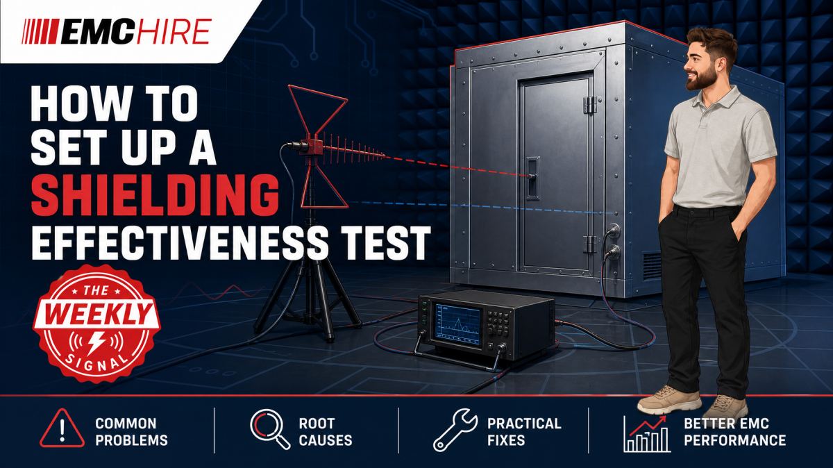
A shielding effectiveness result is only meaningful if the reference path, antenna geometry and enclosure configuration remain controlled. Move an antenna, disturb a cable or exceed the receiver noise floor, and an impressive attenuation figure can become little more than an artefact.
Define what the test is intended to prove
Before assembling equipment, establish whether the objective is to characterise a complete screened enclosure, investigate one penetration, qualify a door or verify remedial work. These are not identical measurements.
Shielding effectiveness is generally derived from the difference between a reference level and the level measured with the shield interposed, expressed in dB. That simple subtraction hides several constraints. The two measurements must represent the same source power, frequency, polarisation, antenna position and propagation geometry. The receiving system must also retain adequate signal-to-noise ratio in the shielded condition.
EN 50147-1 and IEEE 299 are commonly referenced for shielding enclosure measurements, depending on the enclosure, contractual requirements and application. The test team must check the latest active edition, applicable frequency ranges, test positions, antenna arrangements, dynamic-range provisions and reporting requirements. A customer specification may modify or add to the standard method.
Do not assume that a single figure describes every shielding mechanism. At lower frequencies, magnetic-field performance can dominate. At higher frequencies, apertures, seams, connectors and waveguide effects often control leakage. Results should therefore be reported against frequency, position and polarisation rather than reduced prematurely to one headline value.
Establish the reference measurement first
The reference measurement defines the unshielded coupling between source and receiver. Depending on the method, this may be taken before the enclosure is completed, through an open door, at an equivalent free-space geometry or using another arrangement prescribed by the applicable procedure.
Fix the source and receive locations mechanically. Record antenna height, separation, polarisation, orientation and distance from conductive boundaries. Photographs help, but dimensions are better. A photograph alone rarely proves whether an antenna moved by 100 mm between runs.
Reflections complicate the reference. In a chamber, building or test bay, small positional changes can place the receive antenna at a different point in the standing-wave pattern. The resulting level change may then be attributed incorrectly to shielding. Spatial averaging, multiple positions or antenna stirring may be required by the selected method, particularly where enclosure dimensions support resonant behaviour.
Reference levels should be checked across the planned frequency sweep before the shielded measurement begins. This exposes amplifier compression, poor antenna match, cable resonances and frequencies where the received signal is already too close to the measurement noise floor.
Select antennas for the field mechanism
No single antenna covers every shielding effectiveness test setup with predictable behaviour. Antenna type must suit the frequency band, required field component, available spacing and enclosure dimensions.
Loops are commonly used where magnetic-field coupling is being assessed at lower frequencies. Dipoles, biconical antennas, log-periodic antennas, horns and other calibrated or suitably characterised antennas may be used across higher-frequency bands as the method requires. EMC Hire provides access to suitable HF and VHF antennas and UHF and microwave antennas for defined measurement ranges.
Antenna factor alone does not make an antenna suitable. Check physical size, usable frequency range, power rating, connector performance and whether the intended separation places the antennas in an appropriate field region for the selected method. Electrically large antennas squeezed against an enclosure wall can couple directly into seams and penetrations, producing a result dominated by geometry rather than representative enclosure performance.
Polarisation must remain controlled. Testing only one polarisation can miss leakage from a slot whose orientation couples weakly to that field. Doors, panel joints and ventilation apertures often behave differently for orthogonal polarisations.
Protect dynamic range without overdriving the system
The measurement system needs enough usable dynamic range to resolve the expected attenuation. If the reference signal is -20 dBm and the shielded signal disappears into a -90 dBm noise floor, the system cannot substantiate 90 dB of shielding. It can demonstrate only a lower bound after accounting for noise margin and measurement uncertainty.
Increasing source power may help, but only within the ratings and linear operating regions of the generator, power amplifier, cables, connectors and transmitting antenna. Harmonics from an overdriven amplifier can create misleading responses at frequencies that were not intentionally generated. Receiver overload during the reference measurement is equally damaging because compression reduces the apparent reference level and understates shielding effectiveness.
Use attenuation, preamplification and filtering deliberately. Record every setting. If an attenuator is removed for the shielded measurement, its characterised insertion loss must be included correctly. A spectrum analyser or receiver should use settings appropriate to the signal and method. Resolution bandwidth, detector, dwell time and sweep behaviour affect sensitivity and repeatability, so they cannot be changed casually between reference and shielded runs.
Test equipment used for quantitative work should have suitable calibration and known frequency coverage. EMC Hire uses test equipment with calibration traceable through an appropriate ISO/IEC 17025 accredited calibration provider. That traceability supports repeatability, comparison with later formal work and a stronger engineering evidence trail. It does not remove uncertainty caused by poor positioning or uncontrolled propagation.
Control cables, penetrations and support equipment
Cables can bypass the shield under test. A receiver cable routed through an untreated opening may carry RF directly into or out of the enclosure, making the measured leakage a property of the temporary installation rather than the screen.
Where practicable, locate battery-powered receiving equipment inside the enclosure and transfer data by an appropriately filtered or non-conductive path. If cables must cross the boundary, use the intended filtered penetration, fibre link or waveguide-beyond-cut-off arrangement, subject to the applicable method. Any temporary penetration must be documented.
Keep RF cables away from transmitting antennas and suspected leakage points unless the procedure requires otherwise. Secure them so they cannot move during the frequency sweep. Cable movement changes common-mode coupling and can shift the indicated level by enough to mask a marginal seam defect.
The enclosure itself must be in a defined condition. Close doors using the normal latching sequence. Fit production panels, filters, ventilation assemblies and connector plates. Remove temporary conductive tape unless it represents the assessed configuration. A test performed with every seam taped may diagnose the structure, but it does not characterise the untreated enclosure.
Use the frequency sweep to find mechanisms, not just minima
A swept measurement reveals frequency-dependent behaviour, but sweep resolution must be fine enough to detect narrow resonances. Large chambers and screened rooms can exhibit sharp peaks and nulls. A coarse sweep may step over a leakage maximum and report an optimistic minimum shielding value.
Start with an exploratory sweep to identify broad behaviour and local ambient signals. Follow it with narrower investigations around discontinuities, resonances and frequencies close to the acceptance criterion. Where a synthesised source and receiver are used, confirm frequency synchronisation and settling time. Sweeping faster than the amplifier, receiver or control software can settle creates artificial dips.
Ambient noise needs separate assessment, particularly when the source is outside and the receiver is inside. Switching the source off at selected frequencies distinguishes the injected signal from internal electronics, broadcast services and test equipment emissions. If the measured shielded level does not change when the source is disabled, there is no defensible attenuation result at that point.
Locate leakage before changing the design
A failed attenuation trace identifies a frequency and test position, not necessarily the defective feature. Leakage investigation may use a receiving antenna, near-field probe or other suitable detector moved around door seals, corners, ventilation panels, filters and cable entries while the source remains stable.
Probe orientation matters. A magnetic-field probe rotated by 90 degrees may become nearly blind to the local field component. Maintain a repeatable stand-off distance because probe response changes sharply close to a seam.
Temporary conductive foil or absorber can help isolate a path, but each change should test one hypothesis. Covering several joints simultaneously may improve the reading without revealing which joint was responsible. Once the mechanism is understood, remove temporary treatments and repeat the formal geometry with the intended construction.
Typical scenario
Consider an illustrative test of a modular screened room with a personnel door, mains filter, ventilation honeycomb and fibre penetration. The laboratory needs to assess shielding performance over several bands using antenna types appropriate to each band.
The team first reviews the contractual method and defines antenna positions on both sides of each test area. Reference coupling is measured and checked for adequate dynamic range. The room is then closed in its normal operating configuration, with services energised where required and all penetrations fitted as intended.
Suppose attenuation drops around one part of the frequency sweep. Moving the receiving antenna immediately would destroy the controlled comparison. The better approach is to preserve the formal position, verify that the signal is above ambient noise, repeat the point and then begin a separate leakage scan. Door fingers, latching pressure and the ventilation panel can then be investigated individually.
Early investigation makes remedial work cheaper. A bonding or aperture problem found before the room is commissioned is easier to correct than one discovered after production equipment, raised floors and fixed services obstruct access.
EMC Hire can support this work through equipment selection, short-term hire, pre-compliance investigation, on-site testing or access to an EMC laboratory for hire. Where a larger or project-specific space is needed, engineers can also discuss the available test facility for hire. The appropriate route depends on enclosure size, required method, transport constraints and the evidence expected by the customer.
When to Hire EMC Equipment
Shielding measurements often require several antenna bands, RF amplifiers, low-loss cables, receivers and accessories for a relatively short test window. Buying all of that equipment for an irregular programme can tie up capital while leaving the organisation responsible for storage, maintenance, servicing and calibration.
Hiring is particularly useful when a laboratory needs to extend its normal frequency coverage, add a second measurement chain or investigate an unexpected leakage band. It also allows the proposed setup to be proven before committing to long-term equipment ownership.
Project peaks matter too. A temporary system can keep development work moving while the laboratory's permanent equipment remains allocated elsewhere. Selection should still be based on frequency coverage, dynamic range, connector and power compatibility, antenna geometry and the required evidence. Hiring unsuitable equipment merely moves the cost from purchasing to lost test time.
Common EMC Testing Mistakes to Avoid
- Changing antenna geometry between measurements: the subtraction then includes propagation change as well as enclosure attenuation.
- Ignoring the noise floor: a trace at ambient level supports only a lower-bound result, not the displayed shielding value.
- Using one polarisation: directional seams and slots may be missed, producing false confidence.
- Allowing cables to move: altered common-mode coupling damages repeatability and can resemble intermittent leakage.
- Overdriving the amplifier: compression and harmonics corrupt the reference and may generate responses at unintended frequencies.
- Running a coarse or excessively fast sweep: narrow chamber resonances may be missed, while unsettled instrumentation creates artificial minima.
- Leaving the enclosure configuration undefined: undocumented door positions, panels or temporary tape make later reproduction impossible.
- Recording only the final graph: without source power, receiver settings, antenna details, cable losses, positions and ambient checks, the evidence trail is weak.
Frequently Asked Questions (FAQs)
Can a spectrum analyser be used instead of an EMI receiver?
Often, provided it offers adequate sensitivity, selectivity, linearity and traceable amplitude performance for the chosen method. The test plan must define suitable bandwidth, detector and sweep settings. Instrument suitability should be demonstrated rather than assumed from frequency coverage alone.
How much dynamic range is needed?
Enough to exceed the expected shielding attenuation while retaining margin above the shielded-condition noise floor. Include cable loss, antenna performance, amplifier output and receiver linearity. Where the signal cannot be resolved, report a justified lower bound rather than an unsupported exact value.
Should measurements be made at one enclosure position?
Usually not for a complete enclosure assessment. Doors, corners, ventilation panels and service penetrations create different coupling paths. The applicable standard or contractual plan should define positions, polarisations and any spatial sampling requirements.
Can near-field probes provide the formal shielding result?
They are generally better suited to leakage location and comparative debugging than whole-enclosure attenuation measurement. Their local coupling and stand-off sensitivity make results strongly dependent on probe geometry. Use the formal antenna arrangement for the reported shielding result unless the governing method states otherwise.
Does pre-compliance testing prove conformity?
No. It can expose leakage paths, provide calibrated engineering data and improve confidence before formal testing, but it does not automatically establish compliance. Manufacturers remain responsible for identifying applicable legislation, product standards, conformity routes and technical file requirements.
When is on-site testing preferable?
On-site testing is often appropriate for fixed screened rooms, large cabinets, installed medical or industrial environments and structures that cannot be transported without changing their bonding. Site ambient conditions and available antenna clearances must be assessed before fixing the method.
Plan the measurement before booking test time
A defensible shielding effectiveness test setup starts with the required evidence, not the available instruments. Define the enclosure configuration, applicable method, frequency bands, antenna positions, dynamic range and reporting detail before energising the source.
EMC Hire can help laboratories review equipment requirements, arrange a hire quotation, plan on-site measurements, undertake pre-compliance work or discuss formal compliance testing where appropriate. Support is also available for booking space at the EMC Hire test facility. Contact the engineering team on +44 (0)1462 817111 or email sales@emchire.co.uk.
Disclaimer: Content is for informational purposes only and does not constitute formal engineering or regulatory advice. Always verify testing procedures against current official standards (e.g., ISO, MIL-STD, DEF STAN). EMC Hire Limited accepts no liability for outcomes resulting from the use of this information.