


Mains filter placement rules that actually matter
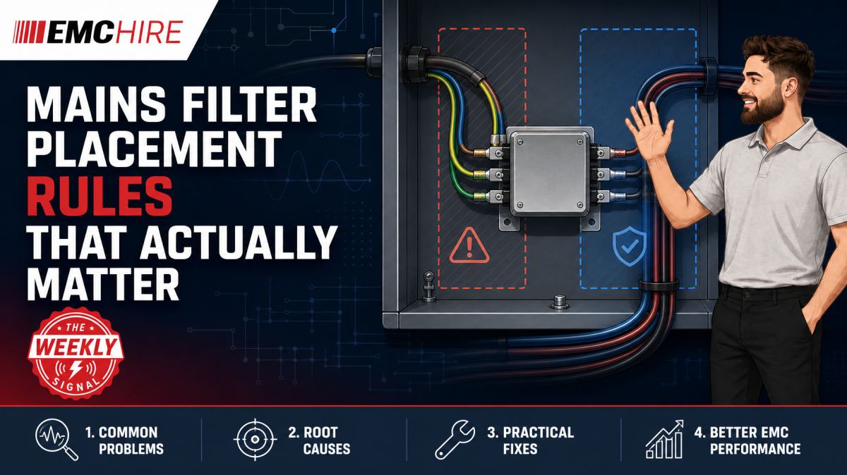
A good mains filter can lose most of its high-frequency attenuation when a few centimetres of wiring, a painted panel or one poorly routed cable provides an easier coupling path around it.
Mains filter placement is therefore not a packaging detail. The physical installation forms part of the filter circuit, particularly once parasitic inductance, chassis impedance and capacitive coupling become comparable with the intended component impedances.
Why filter datasheet performance rarely survives a poor installation
Insertion-loss curves are normally measured in controlled fixtures with defined source and load impedances. A real power converter, motor drive or switched-mode supply presents neither a stable source impedance nor a convenient resistive load across the full emissions band. Common-mode and differential-mode currents also encounter different return paths.
The installed result depends on the filter topology, its source and load termination, the impedance of the protective-earth and chassis structure, and the physical separation between unfiltered and filtered conductors. A datasheet showing strong attenuation does not mean the same attenuation will appear in the equipment.
This becomes especially noticeable in conducted emissions work, commonly undertaken from 150 kHz to 30 MHz where required by the applicable product or product-family standard. A line impedance stabilisation network, or LISN, provides the specified measurement impedance and receiver coupling for relevant power ports. It does not correct a poor filter installation.
Always establish which standard applies before selecting limits, detector types, receiver bandwidths or operating modes. CISPR 11 and CISPR 32 are examples containing conducted emissions requirements for products within their respective scopes, while IEC 61800-3 addresses adjustable-speed electrical power drive systems. None should be assumed to apply simply because equipment is mains powered. Check the latest active edition, product scope, port applicability, limits, configurations and documentation requirements.
Put the filter at the cable entry point
The line side of the filter should normally be kept within a tightly controlled dirty zone at the enclosure entry. If the incoming mains cable crosses the enclosure before reaching the filter, it can radiate internally and couple noise back onto itself. The filter may then attenuate current through its intended circuit while the installation creates a second path around it.
Mounting the filter close to the entry point also reduces the area enclosed by the incoming conductors and their return path. Smaller loop area means lower magnetic coupling. This matters where high di/dt switching currents are present nearby, particularly around bridge rectifiers, power-factor-correction stages, inverter switching nodes and transformer windings.
Do not route the line side and load side together in the same loom, trunking or cable tray. Parallel runs create capacitive and inductive coupling across the filter boundary. Even modest stray capacitance can have sufficiently low impedance at the upper end of the conducted emissions range to bypass part of the filter response.
A practical layout creates two recognisable regions:
- The unfiltered line side extends only from the connector or cable gland to the filter input.
- The filtered load side runs away from the entry and towards the power electronics.
- The two cable groups do not cross or share a bundled route.
- Any unavoidable crossing is short and, where practical, close to 90 degrees.
Short leads only help when the return path is controlled
The instruction to use short leads is sound, but incomplete. Lead length matters because every conductor has inductance. At radio frequencies, the resulting impedance can prevent shunt capacitors from returning common-mode current to the intended reference.
Shortening the live and neutral conductors while leaving a long, narrow filter earth strap may achieve little. A 100 mm bonding path is not merely a piece of copper with negligible DC resistance. Its high-frequency inductance can dominate the connection, allowing the filter body to move electrically relative to the chassis.
Width usually matters more than thickness for a high-frequency chassis bond. A broad, direct metal-to-metal mounting interface generally has lower inductance than a round wire or narrow braid of similar length. The preferred arrangement is often direct fixing of the filter case to a conductive chassis wall, using the mounting method specified by the filter manufacturer.
Paint, anodising, powder coating and contamination can isolate that interface. Star washers may improve local contact, but they do not automatically produce a repeatable low-impedance bond over the service life of the equipment. Surface preparation, corrosion control, fixing pressure and production inspection all need consideration. Protective-earth safety requirements remain separate and must not be compromised while optimising RF bonding.
The chassis bond is part of the common-mode filter
Many mains filters use capacitors from line conductors to the filter case or protective-earth reference. Their effectiveness depends on the current completing a low-impedance path through the chassis and back to the noise source. A poor chassis bond inserts impedance directly into that loop.
This is why a filter can appear satisfactory for differential-mode noise yet disappoint on common-mode emissions. Differential-mode current flows mainly between live and neutral. Common-mode current flows in the same direction on both conductors and returns through chassis, protective earth, cable capacitance or surrounding structures. The two mechanisms require different diagnosis.
A current probe can help compare common-mode and differential-mode behaviour during development, provided the measurement arrangement and probe bandwidth are suitable. Clamping both live and neutral together tends to reveal their net common-mode current because opposing differential currents largely cancel. Measuring conductors separately gives a mixed result and should not be mistaken for a pure mode separation.
Keep safety in view. Mains measurements require suitable probes, rated accessories, controlled access and a test method that does not expose personnel or equipment to unacceptable hazards. Never defeat protective-earth arrangements to obtain a cleaner plot.
Return-path mistakes that bypass the filter
Noise does not follow the schematic. It follows the available impedance network, including parasitic capacitance to heatsinks, cable screens, mounting plates and external loads.
A switched device mounted to an enclosure through an insulating pad may still capacitively inject current into the chassis. That current can return through the mains cable, producing common-mode emissions. If the filter case is poorly bonded, the current may choose an external protective-earth path instead of the intended local route.
Cable screens create another trap. Terminating a screen with a long pigtail adds inductance and weakens high-frequency screening. Routing the screen connection deep inside the filtered compartment can also carry external current across the clean boundary. Where the equipment architecture permits, a circumferential screen termination at the enclosure entry usually controls this path more effectively than a long drain wire.
Metal subassemblies need deliberate bonding. Relying on hinge contact, loose fasteners or mounting rails can produce a configuration that changes after transport or maintenance. The resulting emissions failure may appear intermittent because panel pressure alters the RF impedance without changing DC continuity noticeably.
Typical scenario
Consider an illustrative three-phase drive controller that fails conducted emissions after a mechanically driven redesign. The approved filter part number has not changed, but the enclosure layout has. To simplify assembly, the filter has moved 250 mm from the mains entry, with line-side and load-side conductors sharing a wiring duct.
The engineering team first needs to determine whether the dominant disturbance is common mode, differential mode or a combination. A representative setup would include the applicable LISN arrangement, an appropriate measuring receiver or spectrum analyser used with suitable filtering and detectors, current probes for diagnosis, and the normal cables, loads and operating modes. The formal measurement settings must follow the applicable product standard rather than arbitrary analyser defaults.
Replacing the filter immediately may hide the real fault. A higher-current or higher-attenuation part could still be bypassed by the shared cable route. Moving the existing unit to the entry panel, separating the line side from the load side and restoring a broad chassis bond may be a more informative experiment.
Development measurements should record cable positions, filter orientation, bond preparation, load state and switching mode. Without those records, an apparent improvement cannot be reproduced confidently at formal testing or in production.
EMC Hire can support this investigation through equipment hire, accessible pre-compliance work, on-site testing and test facility access. Suitable instrumentation may include receivers, LISNs and current probes, while higher-power immunity or RF investigation programmes may also require correctly selected RF amplifiers covering DC to 1 GHz, microwave power amplifiers covering 1 to 18 GHz or RF amplifiers and pre-amplifiers. Amplifiers are not substitutes for a conducted emissions receiver or LISN, but they can form part of separate, applicable immunity and low-level diagnostic systems.
Early investigation reduces the chance that tooling, harness drawings and enclosure metalwork will be frozen around an unsuitable layout. It can also provide calibrated engineering data before formal compliance testing. Pre-compliance results improve confidence but do not by themselves prove conformity.
When to Hire EMC Equipment
Hiring is often preferable when a mains filter problem has a defined troubleshooting window. Purchasing a receiver, LISNs, probes and accessories for one programme can tie up capital while creating ongoing calibration, servicing, storage and asset-management obligations.
Short-term access also lets the engineer select equipment for the actual mains arrangement, current rating, frequency range and connector system. Improvised interfaces add uncertainty and may create safety or measurement problems. EMC Hire can also supply appropriate mains leads and adaptors where these form part of a suitable, controlled setup.
Rental is particularly useful when:
- project demand temporarily exceeds an internal laboratory's capacity;
- a failure requires additional probes or a second measurement channel;
- testing must be performed on-site because the EUT is large or installation dependent;
- equipment is needed only before a scheduled formal test campaign;
- future programmes may require different current ratings, frequency coverage or coupling arrangements.
EMC Hire uses test equipment with calibration traceable through an appropriate ISO/IEC 17025 accredited calibration provider. Suitable traceable calibration supports measurement accuracy, repeatability and comparison between development and formal work. It also strengthens the recorded evidence available to engineering teams, corporate stakeholders and, where required, regulatory review.
Common EMC Testing Mistakes to Avoid
Treating protective-earth continuity as proof of an RF bond
A milliohm or continuity measurement can confirm a DC connection without characterising its impedance at MHz frequencies. Long straps, narrow conductors and painted joints may pass a safety-related continuity check yet perform poorly as common-mode return paths.
Letting line-side wiring re-enter the clean zone
Unfiltered conductors routed beside filtered wiring capacitively and inductively bypass the filter. The resulting failure can be misdiagnosed as inadequate component attenuation, leading to unnecessary filter changes and increased leakage current or cost.
Using the wrong LISN configuration
The LISN must suit the supply, port, current and applicable method. Incorrect termination, phase selection or protective-earth arrangement changes the measurement impedance and can produce non-repeatable or invalid conducted disturbance voltage results in dBµV.
Scanning with unsuitable detector and bandwidth settings
Peak detection is useful for exploratory sweeps, while quasi-peak and average detectors may be required for final comparisons under relevant CISPR-based requirements. Resolution bandwidth must match the applicable standard and frequency range. A convenient analyser preset is not evidence that the setup is correct.
Testing an unrepresentative operating mode
A converter at idle may generate a different switching spectrum from the same unit at rated load, during regeneration or under rapidly changing demand. Missing the worst credible mode creates false confidence and leaves the compliance evidence vulnerable.
Failing to photograph cable and bond positions
Small routing changes can move a narrowband emission by several decibels or alter broadband coupling. Reports should identify EUT mode, load, firmware, accessories, cable lengths, routing, bonds, filter orientation and instrument settings. Without that information, later teams cannot reproduce the result.
From troubleshooting data to formal evidence
Once the coupling path is understood, formal compliance testing can confirm performance using the required configuration and current standard. Robust evidence may support the technical file, EMC risk assessment, Declaration of Conformity, mitigation records, customer requirements and self-certification processes where applicable.
The manufacturer or responsible economic operator remains responsible for identifying applicable legislation, standards, conformity assessment routes and documentation. Testing alone does not complete every CE marking, UKCA marking or other market-access obligation. Product-specific requirements, test levels, frequency ranges, equipment configurations, limits and customer test plans should be checked against the latest published documents. General information is available through the IEC electromagnetic compatibility resources, but the current standard itself remains the controlling technical reference.
For defence, automotive and aerospace programmes, pre-compliance work can isolate installation problems before expensive programme testing. Final evidence may need to come from an appropriately accredited laboratory where contractual, regulatory or programme requirements demand it.
Frequently Asked Questions (FAQs)
How close should a mains filter be to the inlet?
As close as the mechanical and safety design reasonably permits, with the unfiltered conductors confined to the entry zone. There is no universal maximum lead length. Judge the layout by loop area, separation, bond impedance and the frequencies being controlled.
Can I connect the filter case with a protective-earth wire?
A protective-earth conductor may be required for safety, but a wire alone may provide a poor RF bond because of its inductance. Direct metal-to-metal case mounting or a short, broad bonding connection is generally more effective at high frequencies, subject to the manufacturer's installation instructions and applicable safety requirements.
Why did a larger filter make the emissions worse?
Source and load impedance can interact with the filter network, producing resonances or moving attenuation nulls. A larger filter may also have different leakage capacitance and mounting requirements. First confirm the noise mode, termination conditions and installation before selecting solely from a nominal insertion-loss curve.
Should line and neutral be twisted on both sides?
Twisting can reduce differential-mode loop area, but it does not justify routing line-side and load-side conductors together. Maintain physical separation across the filter boundary. The optimum arrangement also depends on insulation, temperature, current and mechanical requirements.
Can pre-compliance conducted emissions data support self-certification?
Calibrated, well-documented engineering data may contribute to a technical file and self-certification assessment where that route is legally and technically appropriate. It does not automatically demonstrate compliance. The manufacturer must assess the applicable legislation, standards, risks and evidence as a whole.
When should testing move from the bench to a formal setup?
Move once the dominant paths are understood, representative operating modes are available and the production-intent filter, enclosure, cables and bonds can be tested. Formal work performed too early often consumes laboratory time proving that an unfinished installation is unfinished.
Discuss the installation before changing the filter
If a filter performs well on paper but poorly in the equipment, send EMC Hire the schematic, filter data, enclosure layout, supply arrangement and available emissions plots. The engineering team can help review the likely coupling path, select suitable hire equipment, arrange on-site investigation, plan pre-compliance work or discuss formal compliance testing where appropriate.
To request an equipment hire quotation, book space at the EMC Hire test facility or discuss an on-site test, call +44 (0)1462 817111 or email sales@emchire.co.uk.
Disclaimer: Content is for informational purposes only and does not constitute formal engineering or regulatory advice. Always verify testing procedures against current official standards (e.g., ISO, MIL-STD, DEF STAN). EMC Hire Limited accepts no liability for outcomes resulting from the use of this information.