


Automotive EMC for EVs and hybrids
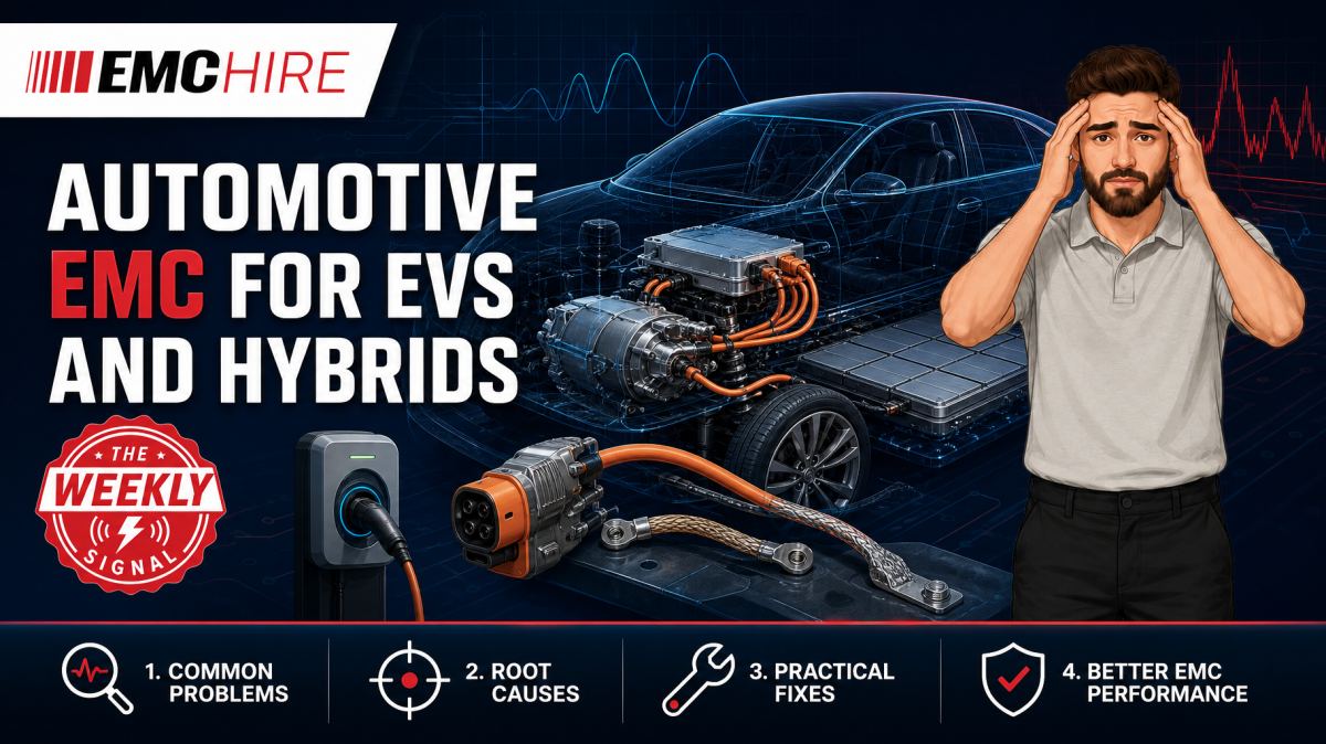
An inverter can meet its bench specification yet disrupt vehicle communications once its high-voltage cables, motor and chassis form the real common-mode current path.
That gap between component behaviour and installed behaviour is where many EV EMC programmes lose time.
Why electrified drivetrains change the EMC problem
Electric vehicles and hybrids combine high switching power, sensitive communications, distributed control electronics and large conductive structures. The resulting EMC environment is materially different from that of a conventional low-voltage vehicle.
The traction inverter is usually the most obvious noise source. Fast semiconductor switching produces high dV/dt and dI/dt, with spectral content extending far beyond the fundamental switching frequency. Silicon carbide devices can improve conversion efficiency, but their rapid edge rates also increase capacitive common-mode currents unless the module, busbar, cable screens, motor and chassis interfaces are engineered as one system.
Noise does not remain inside the inverter enclosure. Parasitic capacitance between switching nodes and the heatsink, motor windings and stator, battery structure and vehicle body provides a return path. A few nanohenries of bonding inductance can matter when current edges are fast. Long pigtail screen terminations are particularly damaging because their impedance rises with frequency, weakening the enclosure-to-cable transition precisely where effective screening is needed.
EV EMC work therefore needs to consider the complete coupling path:
- source characteristics, including switching frequency, edge rate and modulation strategy;
- paths through high-voltage cables, low-voltage supplies, shields, coolant lines and mechanical structures;
- susceptible receivers such as AM/FM and digital radio, GNSS, radar, keyless entry, battery monitoring and in-vehicle networks;
- return-current geometry across enclosures, subframes, battery housings and the vehicle body.
Treating the inverter as an isolated box can produce misleadingly clean results. The vehicle installation may add cable length, resonances and bonding impedances that were absent from the component test.
Inverter noise and high-voltage cable architecture
High-voltage cabling is often screened, but screen effectiveness depends on termination quality rather than the presence of braid alone. A low-impedance 360-degree termination at the connector generally controls high-frequency common-mode current more effectively than a drain wire or pigtail. Paint, anodising, gasket construction and connector backshell assembly can all compromise the intended bond.
Motor phase cables are another concern. Differential-mode current follows the intended phase conductors, while common-mode current seeks a return through cable screens, motor bearings, housings and chassis capacitance. Poor control can raise radiated emissions and contribute to bearing currents or disturbance on nearby harnesses.
Filters must be evaluated with realistic source and load impedances. A filter that performs well in a 50 Ω development fixture may behave differently when connected to a battery pack, inverter DC link and long vehicle harness. Added capacitance can also move resonances rather than remove them. Current probes, voltage probes and near-field probes are useful during diagnosis, but their data should be interpreted as engineering evidence rather than automatically equated with a formal limit measurement.
Charging creates several operating configurations
A vehicle that passes while driving may still fail during charging. AC charging activates the on-board charger, power-factor correction stage, DC-DC conversion, control pilot circuitry and associated contactors. DC charging changes the active hardware and introduces a cable and external charging system that may form a substantial radiating structure.
Charging communications add another layer. Depending on the implementation and market, the system may use control signalling or power-line communication on conductors already carrying substantial power. Broadband converter noise can reduce communication margin without causing an obvious hard failure. Testing only for resets may miss packet loss, delayed handshakes or intermittent charging negotiation.
The test plan should define charging state, battery state of charge, power level, cable type, cable routing, communications activity, thermal state and auxiliary loads. A low-power idle condition is rarely representative of maximum disturbance. Conversely, the worst emissions condition may occur at an intermediate operating point where modulation, discontinuous conduction or control-loop behaviour changes.
Laboratory safety and test capability also need early review. High-voltage isolation, emergency shutdown, cooling, battery management, fire precautions and power absorption cannot be improvised on the test day. The charging source or load must not introduce ambient noise that masks the vehicle or component result.
Standards, OEM specifications and the test plan
Automotive EMC requirements are rarely defined by one document. UNECE Regulation No. 10 is relevant to electromagnetic compatibility type approval in markets applying the UNECE framework. Component and vehicle programmes may also invoke CISPR 25, CISPR 36, ISO 11452 series methods, ISO 7637 transient methods, ISO 21498 high-voltage electrical disturbance methods, product-specific requirements and detailed OEM standards.
The applicability, edition and limits must be confirmed for the actual vehicle, electronic subassembly, voltage class and market. A generic reference to “automotive EMC” is not a usable test plan. OEM requirements commonly add frequency ranges, severity levels, harness constructions, operating modes and functional performance criteria beyond a basic international method.
ISO 11452 methods address component immunity using defined coupling environments such as absorber-lined shielded enclosures, transverse electromagnetic cells and applicable current-injection arrangements. BCI probes are used where the selected method calls for bulk current injection. They are not substitutes for radiated immunity antennas or for every conducted immunity method. EMC Hire provides further information on ISO 11452 automotive immunity testing and suitable automotive test systems.
Low-voltage transient testing and high-voltage transient testing also need to be separated. Applying a familiar 12 V or 24 V pulse concept directly to a shielded traction supply can produce an invalid setup and potentially damage expensive hardware. The source impedance, coupling network, cable configuration, pulse definition and safety provisions must match the applicable method and OEM test plan.
Always verify the latest active edition, product scope, test levels, frequency ranges, equipment configuration, methods, limits and reporting requirements. Contractual specifications may take precedence within a vehicle programme. The UNECE vehicle regulations framework is a useful official starting point for regulatory context, while controlled copies of standards and OEM specifications should govern the engineering detail.
Pre-compliance work that improves formal test readiness
Early EV EMC investigation should reproduce the dominant installation features without pretending that every development setup is a formal test. Useful work includes characterising common-mode current on high-voltage cables, comparing screen terminations, mapping enclosure leakage, checking low-voltage conducted disturbances and exercising communications during immunity exposure.
Configuration control matters. Record inverter software, switching strategy, torque or load, DC-link voltage, motor speed, cable assemblies, bonding hardware and battery simulator settings. Without those records, an improved result may be attributed to a filter change when the real cause was a software mode or different harness position.
Accessible pre-compliance testing gives engineers room to change one variable at a time. It can reduce the financial risk of discovering a bonding or filter problem during a tightly scheduled formal programme. Calibrated engineering data can also support technical documentation, EMC risk assessment, mitigation evidence and self-certification processes where legally and technically appropriate. It does not automatically prove compliance.
EMC Hire uses test equipment with calibration traceable through an appropriate ISO/IEC 17025 accredited calibration provider. Suitable traceable calibration supports measurement accuracy, repeatability and comparison between development and formal testing. It also produces stronger evidence for engineering reviews, corporate stakeholders and regulatory scrutiny.
Formal compliance testing should be planned as part of hardware commercialisation rather than treated as a final administrative event. The resulting evidence may support a technical file, Declaration of Conformity, customer approval process or market-entry decision. The manufacturer or responsible economic operator remains responsible for identifying applicable legislation, standards, conformity assessment routes and documentation obligations.
Typical scenario
Consider an illustrative traction inverter programme approaching vehicle integration. Component radiated emissions appear manageable, but the integrated vehicle shows interference in a radio band during high-torque operation. The disturbance changes when the motor cable is moved and falls when a temporary bond is fitted between the inverter housing and body.
The evidence points towards common-mode current and installation impedance, not necessarily a defective radio receiver. The team must decide whether to change the connector termination, enclosure bond, cable construction, output filtering or switching control. Replacing parts without measuring the coupling path risks adding cost while leaving the dominant mechanism untouched.
A practical investigation would use suitable current probes and near-field probes to locate the source and compare configurations, followed by representative component or vehicle-level measurements. Cable routing, termination torque, operating load and software state would be photographed and recorded. If immunity is also in scope, that work would use the separate method and equipment required by the applicable ISO 11452 or OEM procedure.
EMC Hire can support this type of programme through automotive EMC testing and equipment hire, pre-compliance engineering, facility access, on-site testing and formal compliance testing where appropriate. Early access to suitable equipment lets the team investigate before committing to tooling or production cable assemblies.
When to Hire EMC Equipment
EV programmes often need specialised equipment for a short development phase: a receiver, current injection probe, RF amplifier, transient generator, artificial network or monitoring instrument may be needed for weeks rather than years. Hiring avoids capital expenditure on equipment whose voltage rating, bandwidth or coupling method may not suit the next platform.
It also reduces storage, servicing and calibration overheads. More importantly, it allows the equipment package to be selected against the defined test method rather than forcing a project around whatever happens to be owned internally.
Rental is particularly useful during integration peaks, supplier fault investigations and preparation for formal testing. EMC Hire can help identify compatible equipment and accessories for the intended procedure. Broader options are outlined under commercial EMC test systems. Availability, ratings and configuration should be confirmed for each project and test window.
Common EMC Testing Mistakes to Avoid
Testing an unrepresentative operating mode
Running an inverter unloaded or charging at minimum power can miss the modulation state that generates the highest disturbance. Record load, speed, state of charge and thermal condition, then justify the selected worst-case modes.
Ignoring high-voltage screen termination geometry
A long pigtail adds inductance and can invalidate an otherwise good cable screen at high frequency. Reassembling the connector differently between tests also destroys repeatability.
Changing cable routing without documenting it
Harness height, separation and proximity to the ground plane or vehicle body alter coupling. An unexplained cable movement can look like a successful filter modification and send the diagnosis in the wrong direction.
Using the wrong injection method
A BCI probe, radiated immunity antenna and transient coupling network create different physical stresses. Substituting one because it is available does not demonstrate performance against the required method and may overstress an unintended port.
Allowing support equipment to dominate the result
Battery simulators, dynamometers, chargers and fibre converters can generate emissions of their own. Ambient checks and support-equipment characterisation are needed, otherwise the EUT may receive a false failure or false confidence.
Leaving the evidence trail until later
Missing photographs, cable positions, software versions and performance observations make reproduction difficult. A plot without a controlled EUT configuration is weak evidence, even when the instrument calibration is current.
Frequently Asked Questions (FAQs)
Should EV EMC testing start at component or vehicle level?
Usually both are needed. Component testing gives controlled, repeatable information and supports early debugging. Vehicle-level work captures installation effects, full cable geometry and interactions that a bench fixture cannot reproduce.
Does a screened high-voltage cable guarantee low emissions?
No. Screen transfer impedance, connector termination, enclosure bonding and return-current continuity determine installed performance. A good cable with a poor pigtail termination can still radiate strongly.
Can pre-compliance data be used in a technical file?
Calibrated, well-documented data can contribute useful engineering evidence where the applicable conformity route permits it. The manufacturer must assess whether the evidence is sufficient and whether formal or accredited testing is contractually or legally required.
Are ISO 7637 tests enough for an EV traction system?
Not automatically. The applicable part, voltage domain, port and OEM specification must be checked. High-voltage systems may require methods addressing disturbances on shielded high-voltage supply lines rather than only conventional 12 V or 24 V transient procedures.
When is on-site EV EMC testing useful?
On-site work is valuable when the vehicle, dynamometer, charger or high-voltage safety infrastructure cannot be moved easily. The limitations of ambient noise, physical geometry and available power must be assessed before relying on the results.
Planning the next test window
If an EV platform, inverter, charger or high-voltage subsystem needs investigation, EMC Hire can help review the test objective, select suitable equipment and decide whether equipment hire, on-site work, pre-compliance support, a facility booking or formal compliance testing is the appropriate next step.
To discuss the configuration or request an equipment hire quotation, contact the EMC Hire engineering team on +44 (0)1462 817111 or email sales@emchire.co.uk.
Disclaimer: Content is for informational purposes only and does not constitute formal engineering or regulatory advice. Always verify testing procedures against current official standards (e.g., ISO, MIL-STD, DEF STAN). EMC Hire Limited accepts no liability for outcomes resulting from the use of this information.