

Radiated emissions and clock spread spectrum
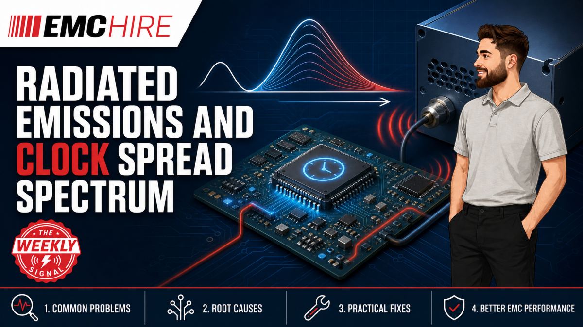
A spread-spectrum clock can lower the highest point on an emissions plot without reducing the total RF energy leaving the product. That distinction explains both its usefulness and its limitations.
Used carefully, spread-spectrum clocking can recover several decibels of radiated emissions margin around clock-related spectral lines. Used as a late-stage patch, it can hide the dominant peak while leaving poor return paths, cable common-mode current and broadband noise untouched.
What spread-spectrum clocking changes
A conventional clock concentrates energy at its fundamental frequency and harmonics. Real clock edges are not sinusoidal, so their spectral content can extend far beyond the nominal clock frequency. A 25 MHz clock with sub-nanosecond edge transitions may contribute measurable energy at harmonics hundreds of megahertz above the fundamental.
Spread-spectrum clocking deliberately modulates the clock frequency over a defined range. Instead of placing most periodic energy into narrow spectral lines, the modulation distributes that energy across a wider bandwidth. The peak amplitude observed by an EMI receiver may therefore fall, even though the integrated energy has not necessarily reduced by the same amount.
This is the basis of spread spectrum EMC. It changes how clock-related energy is distributed in frequency. It does not repair the physical coupling mechanism that allows that energy to reach an enclosure seam, external cable or PCB edge.
Down-spread and centre-spread modulation
Down-spread modulation moves the instantaneous clock frequency below the nominal value. It is often selected where exceeding the nominal maximum frequency would breach a processor, memory, serial interface or regulatory timing constraint. The average operating frequency may be slightly lower, which can affect throughput-sensitive systems.
Centre-spread modulation moves the clock above and below its nominal frequency. This can preserve the nominal average more closely, but the upper excursion must remain within the permitted tolerance of every affected device and interface. A clock generator setting that is acceptable for one processor may not be acceptable for a tightly specified communications link.
Modulation depth and modulation rate both matter. Greater deviation can distribute energy across more frequencies, but it also produces greater instantaneous clock variation. The modulation profile, whether triangular or otherwise, influences the spectral shape. Engineers should use the clock-device manufacturer's characterisation data rather than assuming that two devices with the same percentage setting will produce equivalent emissions results.
Why radiated emissions may improve
Clock energy rarely radiates efficiently from a short PCB trace alone. The more troublesome path is often conversion into common-mode current. Discontinuities in the return path, poorly bonded shields, connectors crossing reference-plane gaps and cables attached near noisy circuitry can turn a modest differential signal into an effective antenna system.
Spreading the source spectrum can reduce the amplitude at individual harmonics measured during a radiated emissions test. The improvement depends on receiver bandwidth, detector behaviour, dwell time, modulation rate and the coupling path. A spectrum analyser sweep configured for debugging may show a larger apparent reduction than a standards-based receiver measurement using the required detector and measurement bandwidth.
Peak detection is useful for fast investigation, but compliance decisions may require quasi-peak, average or other specified measurements, depending on the applicable product standard and frequency range. Spread spectrum can interact with detector charge and discharge characteristics in ways that make a simple peak-marker comparison misleading. Final settings must follow the applicable standard, not a convenient analyser preset.
Radiated emissions commonly begin at 30 MHz, but the upper frequency, antenna arrangement, test distance and detector requirements depend on the product, its highest generated frequencies and the applicable product or product-family standard. The current published requirements must be checked for the actual equipment under test.
Where spread spectrum does not help
Broadband noise from switch-mode power conversion, motor commutation or random data activity will not usually respond to clock spreading in the same way as a coherent clock harmonic. Nor will modulation correct ringing caused by impedance discontinuities, excessive drive strength or poor termination.
Cable radiation can remain largely unchanged if common-mode current is dominated by return-path imbalance rather than the clock's narrowband spectral amplitude. Likewise, an enclosure resonance may be excited across enough of the modulation range that the measured benefit is small.
Conducted disturbances also need separate assessment. Power-port measurements made with a LISN under the applicable conducted emissions test configuration may reveal clock-related components, but a reduction in radiated peaks does not demonstrate a reduction in conducted disturbance voltage. Each coupling path requires its own measurement.
Timing, interface and functional side effects
Frequency modulation introduces deterministic clock variation. Digital design teams must confirm that the complete clock tree, not merely the oscillator, remains within tolerance. PLL tracking behaviour, memory timing, serial link recovery and peripheral clock limits all need review.
Potential side effects include:
- Reduced timing margin at the extremes of the modulation excursion.
- Additional phase modulation or jitter at downstream PLL outputs.
- Loss of lock where a receiving PLL cannot track the modulation profile.
- Changes to serial-link eye opening, bit-error performance or protocol timing.
- Beat products where several independently modulated clocks interact.
- Lower average processing throughput when down-spread operation is used.
- Audio or sensor interference if the modulation rate enters a susceptible baseband path.
A system that boots and passes a short functional check has not necessarily been validated. Temperature, supply tolerance, device variation and high-load operating modes can expose reduced timing margin. Review the oscillator, processor, FPGA, memory and interface manufacturer documentation for permitted clock deviation and jitter treatment.
Measurement strategy for spread spectrum EMC
Start with repeatable A/B measurements. Hold the equipment under test operating mode, cable position, turntable angle, antenna polarisation and software workload constant. Change only the spread-spectrum setting. Otherwise, a few centimetres of cable movement can produce a larger amplitude change than the feature being evaluated.
Use a receiver or analyser with sufficient frequency coverage and suitable detector functions. EMC Hire's tuneable receivers and spectrum analysers can support development investigation when selected for the applicable range and measurement method. Debug sweeps should be followed by measurements using the bandwidth, detector and timing parameters required by the relevant standard.
Near-field probes and current probes can help identify whether the clock energy remains local to the PCB or has coupled onto an external cable. These are diagnostic measurements, not substitutes for the specified radiated emissions setup. Their value lies in locating the mechanism quickly.
Record both enabled and disabled configurations. Capture the modulation depth, rate, profile, clock-generator register settings, firmware revision, EUT operating mode and cable arrangement. If the feature later changes through a firmware update, those records allow the emissions impact to be reassessed.
Equipment used for reportable measurements should have suitable calibration status. EMC Hire uses test equipment with calibration traceable through an appropriate ISO/IEC 17025 accredited calibration provider. This supports measurement confidence, repeatability and comparison between development work and later formal testing. The accreditation relates to the calibration provider or activity, not to the physical instrument itself.
Typical scenario
Consider an illustrative embedded controller that exceeds a radiated emissions limit at harmonics associated with a processor reference clock. The peaks move when the reference frequency changes, and a current probe shows corresponding common-mode current on an external communications cable.
The team enables down-spread modulation and observes lower peak amplitudes during a development sweep. That is promising, but three decisions remain. First, does the reduction remain when measured with the required detector and bandwidth? Second, can every device in the clock domain tolerate the excursion? Third, is the cable current evidence of a return-path problem that should be corrected regardless?
A useful test plan would compare spread spectrum on and off, inspect the PCB and connector return path, measure cable common-mode current, and repeat the radiated scan across representative operating modes. If a connector shield is poorly bonded, fixing that path may provide broader and more stable EMI reduction than clock modulation alone.
Early pre-compliance investigation gives the team room to make that choice before tooling, firmware release or formal testing. EMC Hire can support equipment selection, test-facility access, on-site measurements and practical setup review. Formal compliance testing may then provide evidence for the technical file, Declaration of Conformity and other project documentation where the applicable conformity route permits self-certification.
Testing alone does not complete every CE or UKCA obligation. The manufacturer or responsible economic operator remains responsible for identifying applicable legislation, standards, product configurations and documentation requirements. EMC Hire's CE marking and EMC compliance support can help engineering teams structure the evidence without presenting pre-compliance results as automatic proof of conformity.
When to Hire EMC Equipment
Clock-related emissions faults often require concentrated investigation over several days rather than permanent ownership of a receiver, antennas, preamplifiers, probes and supporting accessories. Hiring provides access to the required frequency coverage and detector capability for a defined development window without committing capital to equipment that may not suit the next programme.
It also avoids long-term storage, maintenance and calibration administration. That matters when an instrument is used irregularly, because an out-of-calibration receiver discovered immediately before a design review is of little practical value.
Rental is particularly effective when project peaks exceed internal laboratory capacity, when engineers need to compare several mitigation options, or when on-site testing is preferable because the EUT is large or difficult to transport. Selection still needs engineering care. An analyser without the necessary detector functions, an antenna outside its characterised range or accessories with insufficient frequency coverage can produce persuasive but unsuitable data.
Hiring also reduces the risk of purchasing around one product's immediate problem. Future programmes may require different upper frequencies, dynamic range, transducers or test methods. EMC Hire can help define a suitable equipment chain, provide pre-compliance support, arrange facility time and discuss formal testing where appropriate.
Common EMC Testing Mistakes to Avoid
Comparing unmatched analyser sweeps
Changing sweep time, resolution bandwidth or detector between the spread-spectrum enabled and disabled measurements invalidates the comparison. Wider bandwidth or longer observation can capture the modulated signal differently, creating an apparent improvement or deterioration that is caused by instrumentation settings.
Treating the tallest peak as the whole problem
A lower harmonic marker does not prove that the product has adequate margin. Sidebands may approach the limit elsewhere, and another orientation or cable position may become dominant. Scan the relevant frequency range and investigate worst-case geometry.
Moving cables between tests
External cables can be the main radiating structure. Repositioning one while changing the clock setting prevents attribution of the result. Photograph, mark and document cable routing so the setup can be reproduced.
Testing an unrepresentative operating mode
An idle processor may use different clock frequencies, spread settings and peripheral states from a fully loaded product. Testing only the easiest mode creates false confidence. Exercise interfaces, displays, memory and communications in modes that credibly maximise emissions.
Ignoring clock-domain compatibility
Enabling modulation without reviewing downstream limits can exchange an EMC failure for an intermittent functional fault. Verify PLL behaviour, timing constraints and interface performance across temperature, voltage and production tolerance.
Using pre-compliance data as final proof
Accessible setups are valuable for debugging and calibrated engineering data, but deviations in site validation, distance, ambient control or configuration may affect comparability with formal testing. Keep the purpose and limitations of each measurement clear in the technical file.
Frequently Asked Questions (FAQs)
How much EMI reduction should spread-spectrum clocking provide?
There is no dependable universal figure. The result depends on modulation depth and rate, receiver settings, clock harmonic order, coupling path and EUT geometry. Measure the actual implementation using fixed, repeatable conditions.
Can spread spectrum turn a failing product into a compliant one?
It may reduce clock-related peaks enough to improve margin, but compliance depends on the complete applicable test programme and product configuration. Treat it as one mitigation technique, not a guaranteed outcome.
Should spread spectrum be enabled during formal testing?
If it is a normal, controlled production configuration and permitted by the product design, it may be appropriate to test with it enabled. The test plan should document the setting and address other user-selectable or worst-case modes. Confirm expectations with the test laboratory and applicable product standard.
Can quasi-peak results differ from peak-scan improvements?
Yes. Detector response, modulation rate, dwell time and measurement bandwidth affect the indicated level. A large change on a fast peak sweep may become smaller when the specified final measurement is performed.
Is centre spread better than down spread?
Neither is universally better. Centre spread can maintain the nominal average frequency but exceeds it during part of the cycle. Down spread avoids an upper excursion but may reduce average throughput. Device tolerances and system timing determine the safer choice.
Which standard should a digital product be tested against?
That depends on product function, intended environment, ports and market. A relevant product or product-family standard may define emissions limits, configurations and operating modes. Check the latest active edition, frequency ranges, limits, detector requirements and contractual conditions rather than relying solely on a generic test method. The IEC electromagnetic compatibility resources provide useful background, but the applicable published requirements must be assessed for the product.
Plan the measurement before changing the clock
Spread-spectrum clocking works best when the offending spectral lines and their coupling path are already understood. Measure first. Then decide whether clock modulation, return-path correction, shielding, filtering, edge-rate control or a combination offers the most robust result.
To discuss receiver or analyser hire, pre-compliance engineering, formal compliance testing, an on-site investigation or space at the EMC Hire test facility, contact the engineering team on +44 (0)1462 817111 or email sales@emchire.co.uk. A review of the clock architecture, suspected frequencies and intended test method will help define a suitable measurement setup before equipment is dispatched or facility time is booked.
Disclaimer: Content is for informational purposes only and does not constitute formal engineering or regulatory advice. Always verify testing procedures against current official standards (e.g., ISO, MIL-STD, DEF STAN). EMC Hire Limited accepts no liability for outcomes resulting from the use of this information.