


What is radiated emissions testing?
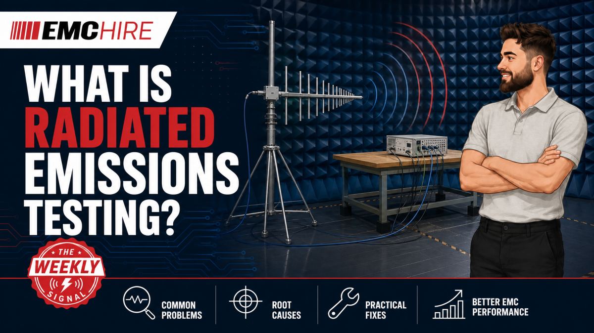
A radiated emissions plot is only meaningful when the antenna, distance, site, cable layout and detector settings represent the applicable test method. Change any one of them and a comfortable margin can disappear.
Radiated emissions testing measures unwanted electromagnetic energy leaving equipment through free space. The objective is usually to determine whether those disturbances remain below limits defined by the applicable product, product-family or regulatory standard.
The measurement is not simply a spectrum analyser connected to an antenna. It is a controlled assessment of the complete equipment under test, or EUT, including its enclosure, ports, cables, peripherals, operating modes and installation arrangement. Each can become part of the radiating structure.
What radiated emissions testing measures
Digital clocks, switch-mode converters, motor drives, data interfaces and RF subsystems generate time-varying currents. When those currents flow through PCB traces, cable shields, enclosure seams or unintended common-mode paths, part of the energy can be radiated.
The receiving antenna converts the incident electromagnetic field into a voltage. A calibrated receiver or suitable spectrum analyser then measures that signal. Antenna factor, cable loss, preamplifier gain and any other characterised components in the measurement path are applied to express the result as electric-field strength, normally in dBµV/m.
Radiated emissions measurements commonly start at 30 MHz, but this is not universal. The upper frequency depends on the applicable requirements, product type and, in some cases, the highest internally generated or intentionally used frequency. Some standards also address radiated disturbances below 30 MHz using different transducers and physical quantities. The current published standard and product-specific requirements must therefore be checked before selecting equipment.
CISPR publications underpin many commercial emissions methods and limits. IEC product and product-family standards may reference CISPR methods or define additional configurations and operating conditions. Standards must be read together with the relevant legislation, contractual specification and product scope rather than treated as interchangeable documents.
Why the antenna changes the result
No single antenna provides optimum sensitivity across every frequency of interest. Biconical antennas are commonly used across lower VHF ranges, log-periodic antennas cover broad higher-frequency ranges, and horn antennas are used at microwave frequencies. The exact breakpoints depend on the antenna model, calibration data and test requirement.
Antenna factor varies with frequency. Using a generic correction table, or the calibration file from a different serial number, directly corrupts the calculated field strength. Cable loss must also be measured or characterised across the test range. At higher frequencies, a seemingly minor coaxial cable or connector change can create a material amplitude error.
Both horizontal and vertical polarisations are normally investigated where required. A cable-driven common-mode emission may be predominantly vertically polarised, while enclosure slots or PCB structures can produce a different response. Measuring one polarisation alone can miss the maximum.
Antenna height scanning and EUT rotation are used in many formal methods to identify the geometry producing the highest received level. This is not procedural theatre. Reflections from the ground plane and chamber surfaces combine with the direct signal, producing constructive and destructive interference. Moving the antenna or rotating the EUT changes that vector sum.
Engineers selecting transducers can review EMC Hire's HF and VHF antennas and broader range of antennas and near-field probes. Near-field probes are useful for localisation during debugging, but their readings are not a substitute for a compliant far-field measurement.
Distance and environment are part of the measurement
Formal test distances are defined by the applicable method and may commonly include 3 m or 10 m arrangements. A result cannot be converted casually between distances using a simple inverse-distance rule. The EUT may not be in the far field across the whole frequency range, while reflections, antenna coupling and site geometry complicate the relationship.
An open-area test site, semi-anechoic chamber or fully anechoic room may be used depending on the standard and frequency range. A semi-anechoic chamber generally has RF absorber on the walls and ceiling with a conductive ground plane. Its performance must be validated for the intended measurements. Merely lining a room with absorber does not create a compliant site.
Ambient radio signals are another source of error. Broadcast, mobile and local digital transmissions can appear as narrowband peaks, particularly during open-site or poorly screened measurements. Switching the EUT off while retaining the measurement configuration helps identify ambients, although intermittent signals still require care.
A GTEM cell can provide a screened and repeatable environment for development work. It is particularly useful for comparative measurements, design iteration and some defined test methods. Physical EUT size, cable routing, field uniformity, mode structure and the method used to derive equivalent radiated data all affect correlation. GTEM results should not automatically be represented as equivalent to chamber data unless the applicable procedure and correlation evidence support that conclusion.
Receivers, spectrum analysers and pre-scans
A spectrum analyser is an effective debugging and pre-scan instrument when its frequency range, dynamic range, overload performance and detector functions suit the work. Formal measurements often use an EMI receiver providing the bandwidths, detectors and measurement behaviour required by the relevant CISPR-based method.
Peak detection is commonly used for rapid pre-scanning because it captures signals quickly and can identify frequencies requiring further investigation. Final assessment may require quasi-peak, average or other prescribed detectors. Resolution bandwidth, video bandwidth, dwell time and scan behaviour must follow the applicable method. Settings chosen simply to make the trace smoother can suppress narrow pulses or reduce the apparent amplitude of intermittent emissions.
Preamplifiers improve system sensitivity but also reduce the available overload margin. A strong fundamental, local transmitter or EUT radio can drive the preamplifier or analyser front end into compression, generating false harmonics or concealing real signals. Input attenuation, filtering and linearity checks are therefore part of a credible setup.
EMC Hire's radiated emissions system information explains the equipment elements involved, while the equipment selection guides provide further support when matching receivers, antennas, cables and accessories to a test window.
Why pre-scan and formal compliance data differ
A pre-scan is intended to expose risk early. It may use a close antenna distance, fixed antenna height, simplified turntable positions or a workshop environment. These compromises improve speed and access, but they change the measured field.
Differences commonly arise from:
- using peak detection during the pre-scan and quasi-peak or average detection for final measurements;
- different antenna distance, height, polarisation or calibration factors;
- uncontrolled reflections from walls, benches and nearby equipment;
- changes to cable length, routing, termination or peripheral equipment;
- different EUT software, data traffic, loading or power conditions;
- ambient signals being mistaken for EUT emissions;
- insufficient dwell time to capture intermittent operating events.
Pre-scan data is most useful when the setup is documented and kept physically representative. Photograph cable positions, record software revisions and list active interfaces. Without that record, a later improvement may be attributed to a PCB change when it was actually caused by moving a cable away from the enclosure seam.
Accessible pre-compliance testing gives engineers time to probe current paths, test shielding changes and compare filter options before the design is frozen. Calibrated engineering data can support design decisions and self-certification processes where legally and technically appropriate, but pre-compliance results do not by themselves prove compliance.
Typical scenario
Consider an illustrative networked controller containing a switch-mode supply, high-speed processor and several external cables. A bench pre-scan shows harmonics close to the anticipated limit, with the strongest response changing when the Ethernet cable is moved.
The team first needs to establish the applicable product or product-family standard, formal test distance, frequency range, EUT arrangement and required detectors. A representative support package, cable set and worst-case software mode must then be defined. Testing only an idle unit would create false confidence because processor activity and interface traffic can change both harmonic content and common-mode cable current.
Near-field probes may locate energy around the processor clock and connector region. A current probe can then help determine whether the external cable is carrying common-mode RF current. Neither measurement is a formal radiated result, but together they provide useful diagnostic evidence.
An early chamber or GTEM investigation can compare bonding, filtering and cable-management changes before tooling is committed. Selecting an unsuitable antenna, using an analyser without adequate sensitivity, or ignoring the required detector response could send the team towards the wrong mitigation.
EMC Hire can support this work through equipment hire, pre-compliance engineering, on-site investigation, test facility access and formal compliance testing where appropriate. For self-certification applications where accredited testing is not specifically mandated, robust test records may contribute to the technical file, EMC risk assessment, Declaration of Conformity process and mitigation evidence. The manufacturer or responsible economic operator remains responsible for confirming applicable legislation, standards and conformity assessment requirements.
When to Hire EMC Equipment
Radiated emissions equipment is often needed intensely for a short development phase and then left unused. Hiring can avoid tying capital up in antennas, receivers, preamplifiers and calibrated cables that may not suit the next programme.
It is particularly practical when a team needs to investigate a defined frequency band, cover a project peak or reproduce a laboratory failure at its own site. The equipment package can be selected for the actual method rather than constrained by whatever analyser or antenna happens to be available internally.
Ownership also brings storage, servicing, damage control and calibration management. EMC Hire uses test equipment with calibration traceable through an appropriate ISO/IEC 17025 accredited calibration provider. Suitable traceable calibration supports measurement accuracy, repeatability and comparison between development and formal testing. It also strengthens the evidence available to engineering teams, corporate stakeholders and regulatory reviewers.
Hiring does not remove the need for a sound test plan. It does reduce the risk of purchasing a system whose frequency coverage, detector capability, sensitivity or accessories prove unsuitable for later programmes.
Common EMC Testing Mistakes to Avoid
Treating cable placement as housekeeping
External cables are often the dominant radiating structure. Coiling excess cable differently between runs changes its impedance, coupling and effective antenna geometry. The resulting plots may be individually repeatable but no longer comparable.
Using an unrepresentative operating mode
A quiet diagnostic mode may suppress displays, communications or motor activity. Passing in that condition says little about the normal worst-case configuration. Exercise interfaces and loads systematically, then record the selected mode.
Applying the wrong antenna correction data
Incorrect antenna factor or cable-loss data shifts the reported field-strength trace. A clean-looking result can therefore be numerically wrong across a broad frequency range.
Ignoring receiver overload
Adding a preamplifier without checking linearity can create intermodulation products and apparent harmonics. Repeat suspicious measurements with additional attenuation or appropriate filtering and confirm that the corrected amplitude remains stable.
Changing geometry while debugging
Moving the EUT, antenna and cables at the same time makes cause and effect impossible to separate. Change one variable, preserve reference photographs and retain raw traces.
Reporting only the final plot
A trace without equipment identification, calibration status, detector settings, antenna geometry, cable configuration and EUT mode is weak evidence. Another engineer may be unable to reproduce it, leaving the technical file with an avoidable gap.
Frequently Asked Questions (FAQs)
Can a spectrum analyser be used for radiated emissions testing?
Yes, particularly for debugging and pre-scanning, provided its frequency coverage, sensitivity, dynamic range and detector implementation suit the task. Formal measurements must use equipment and settings meeting the applicable method, which may favour a compliant EMI receiver.
How much margin should a pre-scan show?
There is no universal margin. Site uncertainty, distance, detector differences, build variation and cable configuration all matter. Set an engineering margin from known setup differences and product risk rather than relying on a fixed rule.
Does a GTEM replace an anechoic chamber?
Not automatically. A GTEM can be highly effective for development and for methods that explicitly support its use. Chamber replacement depends on the product, standard, EUT size, cable arrangement and defensible correlation.
Why does rotating the EUT change the level?
Rotation changes the orientation of radiating currents relative to the antenna and alters the direct and reflected propagation paths. The maximum may occur at an unexpected angle, particularly where cables and enclosure apertures radiate together.
Can near-field probe readings be converted into dBµV/m at 3 m or 10 m?
Not reliably through a simple conversion. Near-field measurements depend strongly on probe geometry, position and local electric or magnetic coupling. They are diagnostic measurements unless a validated modelling or correlation method establishes otherwise.
Which standard should be used?
That depends on product function, intended environment, market and regulatory or contractual requirements. Verify the latest active edition, scope, limits, frequency range, distance, detectors, configuration and documentation requirements. Product-specific standards take priority where applicable.
Planning a defensible measurement programme
EMC Hire can help select a suitable antenna, receiver, preamplifier and accessory package, arrange on-site testing, or provide access to its test facility for pre-compliance and formal compliance work where appropriate. Support is also available for planning measurements that contribute to a clear, reproducible technical evidence trail.
To discuss radiated emissions testing, request an equipment hire quotation or book facility time, contact the EMC Hire engineering team on +44 (0)1462 817111 or email sales@emchire.co.uk.
Disclaimer: Content is for informational purposes only and does not constitute formal engineering or regulatory advice. Always verify testing procedures against current official standards (e.g., ISO, MIL-STD, DEF STAN). EMC Hire Limited accepts no liability for outcomes resulting from the use of this information.