


What a complete radiated emissions setup needs
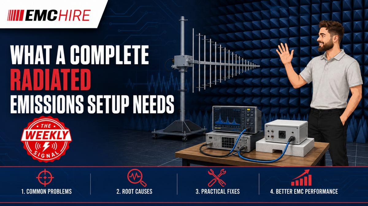
A good receiver cannot rescue a poor radiated emissions setup. Antenna position, cable loss, site performance and EUT configuration can each move the result enough to hide a real problem or create a false one.
Building a complete system therefore means more than selecting an antenna and an EMI receiver. The measurement chain, test environment, positioning equipment, control software and operating procedure must work together over the required frequency range.
Start with the applicable product requirements
Equipment selection should begin with the product or product-family standard, not an instrument catalogue. CISPR publications and related EN standards commonly define radiated disturbance limits and measurement arrangements, while product standards determine which requirements apply to the equipment under test. A generic configuration assembled without checking product scope can be technically impressive and still answer the wrong compliance question.
Radiated emissions measurements commonly begin at 30 MHz, but neither the upper frequency nor the exact method is universal. They may depend on the applicable standard, highest internal operating frequency, product type and intended market. Below 30 MHz, some standards use magnetic-field measurements with loop antennas rather than the electric-field arrangements normally associated with higher frequencies.
Before specifying hardware, establish:
- The applicable product and product-family standards.
- The required frequency range and measurement distance.
- The prescribed antenna types, polarisations and height scan.
- The required detectors, measurement bandwidths and limits.
- Whether testing is required in an open-area test site, semi-anechoic chamber, fully anechoic room or another defined environment.
- The EUT dimensions, power demand, cable layout and operating modes.
- Any above-1 GHz requirements, including absorber, antenna height or test-volume provisions.
Always verify the latest active edition, test levels, limits, configurations and documentation requirements. Standards evolve, and a test plan inherited from an older programme may no longer represent the current route.
The receiving instrument must behave as the method expects
A compliant EMI receiver is normally preferred for formal measurements because it provides the detector functions, bandwidths, overload performance and frequency accuracy needed by the relevant measurement standard. Peak, quasi-peak and average detectors are not interchangeable. Peak detection is useful for fast exploratory sweeps, but a peak result alone does not necessarily determine compliance where the limit specifies quasi-peak or average detection.
A spectrum analyser can be highly effective during development if its dynamic range, detector implementation, resolution bandwidth, frequency coverage and input protection are suitable. It should not automatically be treated as equivalent to an EMI receiver. Fast sweep settings can under-report intermittent or narrow-duration disturbances, while excessive input attenuation can bury low-level emissions in the noise floor.
Preamplifiers can improve system sensitivity, particularly at higher frequencies, but introduce another overload mechanism. A strong ambient transmission or EUT harmonic may compress the amplifier before the receiver indicates overload. Filtering, attenuation and preselection must therefore be considered as a system, not added independently.
For formal or defensible engineering work, EMC Hire uses test equipment with calibration traceable through an appropriate ISO/IEC 17025 accredited calibration provider. Suitable traceable calibration supports repeatability, confidence in recorded data and better comparison between development and formal measurements. It does not correct an invalid site or an unsuitable test configuration.
Antennas define the radiated measurement path
No single antenna is optimal across every frequency range. Biconical, log-periodic, hybrid and horn antennas are commonly selected according to bandwidth, sensitivity, physical size and the applicable method. Loop antennas may be required where magnetic-field emissions are measured. The chosen antenna must also tolerate the site geometry and required height range without contacting absorbers, the ground plane or chamber fittings.
Antenna factor converts the voltage at the receiver into field strength, usually expressed as dBµV/m after cable loss and other applicable corrections have been included. Using the wrong antenna-factor file can shift an entire plot while leaving it visually plausible. Serial-number control matters because correction data belong to the characterised antenna, not merely to its model family.
Polarisation matters too. Horizontal and vertical measurements can expose different current paths on enclosures and cables. Omitting one polarisation can miss the maximum emission. Likewise, fixing the antenna at a convenient height rather than performing the prescribed search may measure a field cancellation rather than the true maximum.
EMC Hire provides a range of HF and VHF antennas, together with broader antennas and near-field probes for measurement and diagnostic work. Near-field probes help locate a source or coupling path on a prototype, but their local measurements do not replace a calibrated far-field compliance result.
Cables, connectors and correction data are part of the instrument
RF cables are often treated as accessories. In measurement terms, they are components of the calibrated signal path. Loss rises with frequency and can change after repeated flexing, connector damage or tight bending. A cable characterised when laid straight may behave differently after being crushed in a chamber door or routed around a mast joint.
Use low-loss cables with suitable connector ratings and sufficient screening. Their length should accommodate the full antenna height and turntable travel without tension, dragging loops or changing geometry during the scan. Excess cable should not be coiled casually beside the antenna, where it may couple to the measured field.
The software correction table must correspond to the actual cable set, antenna, preamplifier and attenuator configuration. Replacing a cable without updating its loss data creates a systematic error. A simple end-to-end check using a known source can also reveal a disconnected preamplifier supply, damaged adaptor or incorrect correction file before a full test day is lost.
The site determines whether the field is measurable
A radiated emissions site must provide the geometry and electromagnetic performance required by the applicable method. Chamber absorber alone does not establish suitability. Reflections from the ground plane, walls, doors, mast, turntable and support furniture influence the field at the antenna.
Site validation and ongoing checks are needed to demonstrate that the environment remains fit for the intended measurements. The precise validation method depends on frequency range, site type and applicable standard. A chamber can change after absorber damage, equipment installation or an apparently minor modification to a cable penetration.
Ambient signals also require control. Broadcast, mobile and other radio services can mask EUT emissions, particularly at an open site or in a chamber with degraded shielding. Recording an ambient scan with the EUT switched off helps distinguish external signals, although intermittent transmissions may still complicate diagnosis. Switching off the EUT is not sufficient if its support equipment continues radiating.
Turntable, antenna mast and EUT support
The turntable rotates the EUT to find the azimuth producing maximum received field strength. It must carry the EUT safely, allow controlled movement and provide position information suitable for repeatable maximisation. A hand-rotated platform may support early debugging, but poor angular control makes it difficult to reproduce a narrow maximum.
An antenna mast must cover the required height range and support both polarisations without excessive movement or metallic disturbance near the antenna. Control cables and motors should not become unintended radiators. Remote operation is particularly useful because opening a chamber door or placing an operator near the antenna changes the test environment.
EUT support tables need the specified height and low electromagnetic influence. Substituting a metal-framed office bench can alter common-mode current paths and reflections. Cable drops, floor proximity and separation from the ground plane must follow the applicable configuration because the cables frequently act as the dominant radiating structure.
Software and records make the result reproducible
Automation can coordinate receiver sweeps, turntable rotation, antenna height and polarisation. It also reduces transcription errors when applying correction data. Automation does not remove the need for engineering oversight. A script will repeat an incorrect bandwidth, detector or correction table with admirable consistency.
Useful records include instrument identities, calibration status, software version, correction-file revision, chamber configuration, antenna distance, photographs, EUT modes, cable positions and support equipment. Preserve exploratory scans as well as final maximised results where they help explain engineering decisions.
For a broader view of integrated hardware, see EMC Hire's radiated emissions system information. Power-port disturbance voltage is a separate measurement discipline using a suitable LISN and receiver, so teams planning both activities should also review the conducted emissions system information.
Typical scenario
Consider an illustrative development team preparing a networked industrial controller for pre-compliance testing. The product contains a switched-mode power supply, a processor clocked at several hundred megahertz and external Ethernet and sensor cables. The applicable product standard requires radiated emissions measurements over a defined range, with the upper frequency determined after reviewing the product requirements and internal frequencies.
The team needs an EMI receiver, appropriate antennas, antenna mast, turntable, characterised RF cables and a suitable test site. A near-field probe set and current probe may also help identify source regions and common-mode cable currents during debugging, although neither substitutes for the specified radiated measurement.
Choosing an antenna that stops below the required upper frequency leaves a known coverage gap. Selecting a spectrum analyser without checking detector behaviour may produce data that cannot be compared directly with the specified limit. If the chamber, measurement distance or cable layout is unrepresentative, design changes based on those results may target the wrong mechanism.
Early investigation allows the team to compare enclosure bonding, cable terminations, clock settings and filter options while PCB or mechanical changes remain manageable. Accessible pre-compliance testing can gather calibrated engineering data and improve confidence before formal compliance work, but it does not by itself prove compliance.
EMC Hire can support equipment selection, short-term hire, facility access, on-site measurements and pre-compliance engineering. Formal compliance testing may also be appropriate for self-certification applications where accredited testing is not specifically mandated. For defence, automotive or aerospace programmes, pre-compliance support can reduce programme risk, while final testing may need an appropriately accredited laboratory depending on contractual or regulatory requirements.
When to Hire EMC Equipment
Hiring is technically sensible when the required frequency coverage, antenna type or receiver capability is specific to one programme. Buying a wideband measurement chain before the long-term workload is known can lock capital into equipment that does not suit the next product family.
Rental also covers short project peaks, chamber investigations and temporary replacement of equipment undergoing service or calibration. It avoids long-term storage, maintenance and calibration overheads for instruments used only a few weeks each year. The hire window should include time for familiarisation, system checks and debugging rather than beginning on the first booked test day.
Specify the complete chain when requesting equipment: frequency range, detectors, antenna types, cable lengths, preamplification, software and connection interfaces. Hiring isolated items without checking compatibility can leave the receiver unable to power the preamplifier or the mast unable to mount the selected antenna.
Common EMC Testing Mistakes to Avoid
Testing only the convenient operating mode
An idle EUT may suppress interfaces, clocks or power stages that dominate emissions in normal service. Exercise representative high-emission modes and document software, loads, ports and traffic conditions. Otherwise, the resulting plot offers false confidence and cannot be reproduced later.
Changing cable routing during maximisation
Uncontrolled cable movement changes common-mode current distribution and radiation efficiency. Secure cables in the prescribed arrangement, photograph them and repeat any defined height or orientation search consistently.
Using the wrong detector or bandwidth
A rapid peak scan is useful for locating frequencies of interest, but final measurements must use the detector and bandwidth required by the applicable standard. Incorrect settings can miss impulsive disturbances or produce results that are not comparable with the limit.
Ignoring overload and noise floor
A low displayed trace does not prove sensitivity. Excess attenuation, cable loss or a failed preamplifier can put the system noise floor above the required measurement level. Conversely, excessive gain can compress the front end. Record noise-floor checks and verify the chain with a known signal.
Losing configuration traceability
Plots without antenna height, polarisation, azimuth, distance, cable arrangement and EUT mode are difficult to defend. Poor records also make redesign evaluation slower because the original condition cannot be recreated.
Frequently Asked Questions (FAQs)
Can one broadband antenna cover the whole test?
Sometimes, but not automatically. Confirm the antenna's characterised range, sensitivity, physical suitability and acceptance under the applicable method. Multiple antennas may provide better performance or be required across a broad frequency span.
Is a spectrum analyser sufficient for pre-compliance work?
It can be, provided its frequency range, bandwidths, detectors, dynamic range and sweep behaviour suit the task. Differences from an EMI receiver must be understood, especially when comparing results with quasi-peak or average limits.
How much margin should a pre-compliance result have?
There is no universal safe margin. Measurement uncertainty, site correlation, prototype maturity, production variation and configuration control all matter. A small apparent pass in an uncontrolled setup should be treated as a development warning, not firm evidence.
Do near-field probes provide radiated compliance data?
No. They are diagnostic tools for locating local electric or magnetic fields and comparing design changes. Their readings normally cannot be converted directly into a compliant far-field result without a much more involved, validated method.
What documentation supports a defensible evidence trail?
Retain the test plan, applicable standard editions, equipment and calibration records, site information, correction data, photographs, EUT operating modes, raw results and engineering decisions. These records may support the technical file, EMC risk assessment, mitigation evidence and Declaration of Conformity where the chosen conformity route permits self-certification. The manufacturer remains responsible for confirming applicable legislation, standards and documentation duties.
Should radiated and conducted emissions be planned together?
Yes, but they remain separate measurements. Conducted emissions on relevant power ports normally use a LISN, while radiated emissions use antennas and a defined site. Common-mode cable currents can connect the underlying design problems, so evidence from one test can guide debugging of the other.
Planning the measurement chain
If you are budgeting a radiated emissions setup, start with the product requirements and the complete signal path rather than a preferred receiver model. EMC Hire's engineering team can help review equipment compatibility, prepare a hire quotation, arrange on-site testing, discuss formal compliance or pre-compliance work, or book space at the EMC Hire test facility.
Call +44 (0)1462 817111 or email sales@emchire.co.uk with the required frequency range, applicable product standard, EUT dimensions and intended test window. That information is usually enough to begin identifying the receiver, antennas, cables, positioning hardware and facility arrangement needed for a credible measurement.
Disclaimer: Content is for informational purposes only and does not constitute formal engineering or regulatory advice. Always verify testing procedures against current official standards (e.g., ISO, MIL-STD, DEF STAN). EMC Hire Limited accepts no liability for outcomes resulting from the use of this information.