

How to compare radiated emissions pre-scan results fairly
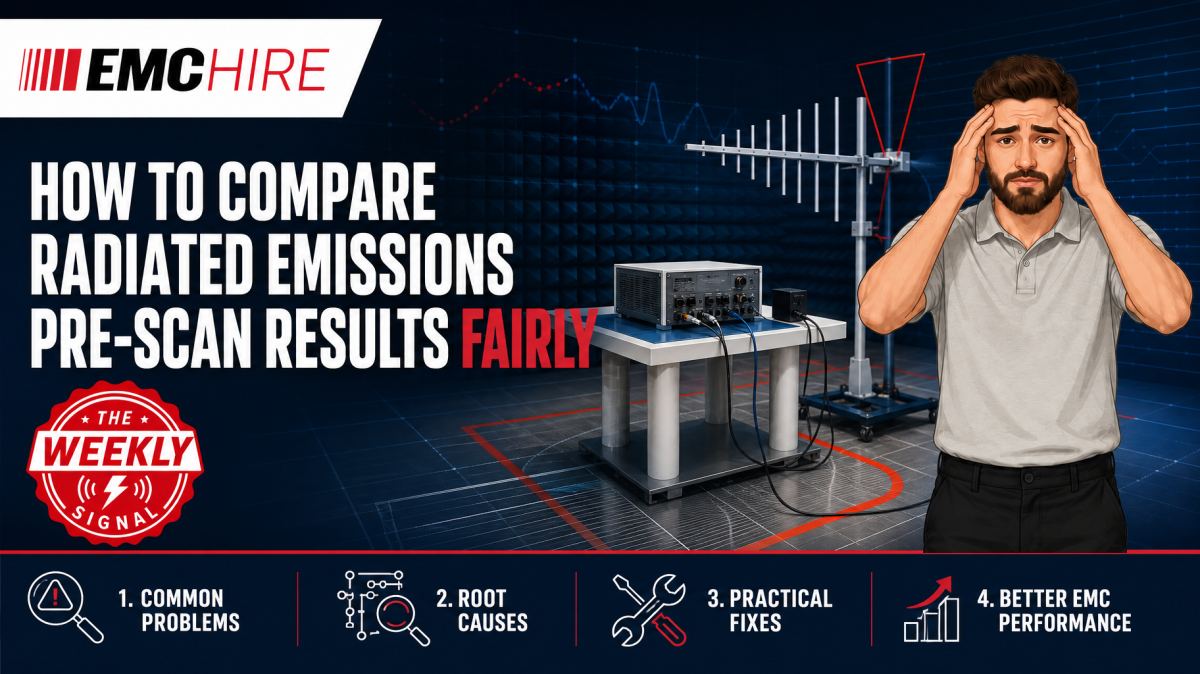
A 6 dB improvement on a radiated emissions pre-scan is meaningless if the cable position, detector, antenna geometry or equipment operating mode changed between measurements.
Trend plots only become useful engineering evidence when the measurement process is controlled. Without that discipline, teams can approve ineffective fixes, reject good designs or arrive at formal testing with false confidence.
What makes two pre-scans genuinely comparable?
A radiated emissions pre-scan measures the combined behaviour of the equipment under test, its cables, the support equipment, the test site and the measurement chain. It does not measure the PCB in isolation. Any change affecting common-mode current, antenna efficiency or receiver response can move the trace.
Fair comparison means holding every material variable constant except the design change being assessed. In practice, this requires a written baseline covering the EUT configuration, operating mode, cable arrangement, antenna position, measurement distance, receiver settings and data processing method.
The applicable product or product-family standard remains the starting point. CISPR 32, for example, may be relevant to multimedia equipment, while other products may fall within different CISPR, EN or IEC requirements. CISPR 16 describes measuring apparatus and methods used by many emissions standards, but it does not by itself define the compliance limits for every product.
Always check the latest active editions, product scope, measurement distance, frequency range, limits, detector requirements, equipment configuration and documentation rules. Customer or contractual test plans may add further conditions.
Fix the EUT operating state before analysing the trace
Modern products rarely have one stable emissions state. Processor loading, display content, radio activity, motor speed, converter load and data traffic can all change the spectrum. A pre-scan taken during an idle state cannot fairly be compared with one captured during sustained processing or maximum I/O activity.
Define the operating mode in enough detail for another engineer to reproduce it. Record firmware revision, clock configuration, enabled interfaces, power source, peripheral activity, representative loads and software test sequence. If the operating cycle is intermittent, establish whether the receiver will use max hold, repeated sweeps or dwell at selected frequencies.
Warm-up also matters. Oscillator frequencies can drift, fan speed may change with temperature and power converters may enter different control modes. Comparing a cold prototype with a thermally stabilised build can create apparent improvements that have nothing to do with the modification under review.
Cable routing can dominate radiated emissions
External cables often act as efficient radiating structures once common-mode current reaches them. Moving a cable by a few centimetres can alter its coupling to the reference ground plane, enclosure and other conductors. The resulting change may be larger than the effect of a filter component or shielding modification.
Use defined cable lengths, terminations, breakout arrangements and support heights. Mark routing positions on the table or support structure and take photographs from repeatable viewpoints. Coiling surplus cable differently between tests changes both current distribution and effective antenna geometry.
Support equipment must be controlled as carefully as the EUT. A laptop charger, monitor or interface adaptor can produce emissions that overlap the frequencies being investigated. Where practical, identify these contributions by switching support items off individually, replacing them with characterised alternatives or using optical isolation.
Antenna geometry and test distance must not drift
Radiated field strength depends on the spatial relationship between the source and receiving antenna. Comparisons should use the same measurement distance, antenna type, polarisation, height and orientation. The EUT must occupy the same position and azimuth reference.
A fixed-height development scan can be useful for rapid fault-finding, but it should not be compared directly with a later scan that includes antenna-height searching and turntable maximisation. The second method is more likely to find a higher field. That does not prove the new build is worse.
Likewise, results from a small screened enclosure, open-area test site, semi-anechoic chamber and workshop bench should not be merged into one trend line without qualification. Site reflections, absorber performance, ground-plane geometry and ambient signals differ. A radiated emissions measurement system may support useful development work, but the setup and its limitations must be documented.
Detector and bandwidth settings change what the receiver reports
Peak, quasi-peak and average detectors do not describe interchangeable measurements. Peak detection responds rapidly and is commonly used for efficient pre-scanning because it will generally identify frequencies requiring closer investigation. Quasi-peak detection applies charge and discharge behaviour intended to weight disturbance repetition characteristics. Average detection measures another aspect of the disturbance and may be required by the applicable standard in defined circumstances.
A peak trace from one build should be compared with a peak trace from another. Comparing it with quasi-peak or average data can produce a misleading trend even when the underlying disturbance has not changed.
Resolution bandwidth affects measured amplitude, noise-floor appearance and the ability to separate adjacent signals. For many CISPR radiated emissions measurements between 30 MHz and 1 GHz, a 120 kHz CISPR bandwidth is commonly associated with the applicable measurement framework. That value must not be assumed outside its defined context. Measurements below or above that range, or under another standard, may require different settings.
Video bandwidth, sweep time, dwell time, frequency step size and detector implementation should also remain fixed. A fast analyser sweep may under-report intermittent or narrow-duration disturbances. Conversely, long max-hold acquisition can capture operating events and ambient transmitters absent from a shorter run.
Keep the complete measurement chain under control
Raw receiver input is not the same as corrected electric-field strength. The final result may include antenna factor, cable loss, preamplifier gain and other characterised path corrections. Using an outdated correction table or applying gain with the wrong sign can move an entire plot while still producing a plausible-looking graph.
Record the antenna serial number or identifier, cable assembly, preamplifier, attenuator settings and receiver configuration. Check that the preamplifier and receiver remain within their linear operating range. Overload can create harmonics, intermodulation products or compression, leading to false failures and false improvements.
EMC Hire uses test equipment with calibration traceable through an appropriate ISO/IEC 17025 accredited calibration provider. Suitable traceable calibration supports measurement accuracy, repeatability and comparison between development and formal testing. It does not remove uncertainty introduced by poor setup control.
Use a comparison protocol rather than visual judgement
Overlay plots are helpful, but a crowded graph can hide frequency shifts or intermittent behaviour. Maintain a table of emissions of interest, including frequency, amplitude, detector, bandwidth, polarisation, antenna position, EUT azimuth and operating state.
Oscillator tolerances may cause a narrowband emission to move between builds. Comparing amplitudes at one exact frequency bin could then suggest a large reduction even though the peak merely shifted. Search within a defined frequency window around the known source and compare the local maximum.
For broadband noise, compare consistent bands or representative maxima rather than isolated bins. Repeat the baseline measurement periodically. If the unchanged reference build moves significantly, investigate the test system and setup before attributing differences to the new design.
Uncertainty should shape the decision. A small change close to normal setup variation is not strong evidence of improvement. Larger, repeatable changes seen across several controlled runs are more persuasive, particularly when supported by current-probe, near-field or conducted diagnostics.
Typical scenario
Consider an illustrative controller that fails a radiated emissions pre-scan around several clock harmonics. The engineering team adds common-mode filtering to an external interface and modifies the enclosure bond. A second scan appears 5 dB lower.
Before accepting the change, the team discovers that the interface cable was routed flat against the ground plane during the second test, while it had previously dropped over the table edge. The detector and receiver settings were unchanged, but the radiating structure was not. The measured reduction cannot be assigned confidently to the filter or bond.
A defensible investigation would restore the original cable route, repeat both configurations, capture horizontal and vertical polarisation data and verify the result at the same antenna positions and EUT azimuths. A current probe measurement on the interface cable could help establish whether common-mode current actually fell.
Early work through an accessible EMC pre-compliance testing service allows modifications to be assessed before enclosure tooling, PCB release or formal testing. Calibrated engineering data can improve confidence and support the technical file, although pre-compliance results do not automatically demonstrate conformity.
EMC Hire can support equipment selection, facility access, pre-compliance investigation, on-site testing and formal compliance testing where appropriate. For self-certification routes such as applicable CE marking arrangements, the manufacturer remains responsible for identifying the legislation, standards, conformity assessment route and documentation requirements. Further practical context is available in EMC Hire's CE marking guidance.
When to Hire EMC Equipment
Hiring is often appropriate when radiated emissions work is concentrated around prototype builds, design reviews or a short formal test window. Purchasing a receiver, antennas, preamplifiers, cables and supporting equipment for irregular use can tie up capital while creating ongoing storage, servicing and calibration responsibilities.
Defined hire periods also let a team select equipment for the actual frequency range and measurement method instead of trying to adapt an unsuitable instrument bought for an earlier programme. That reduces ownership risk when future products require different antennas, receiver performance or test methods.
Project peaks are another common reason. Temporary access to an additional measurement chain can keep parallel builds moving without compromising the main laboratory schedule. Equipment hire may be combined with facility booking or engineering support where the team needs help establishing a repeatable setup.
Radiated debugging sometimes reveals a cable-borne source that warrants separate investigation. In that case, a correctly configured conducted emissions system and LISN may be used for relevant power-port voltage measurements. A LISN is not a radiated emissions transducer and should not be treated as one.
Common EMC Testing Mistakes to Avoid
Comparing different detector traces
A lower average or quasi-peak result does not prove improvement against an earlier peak trace. Preserve detector identity in filenames, plot legends and result tables.
Changing cables without recording their position
Cable movement changes common-mode radiation and coupling to the ground plane. Photographs, position marks and controlled lengths provide far better repeatability than a note stating only that cables were arranged typically.
Allowing analyser settings to follow saved defaults
Saved states can contain the wrong bandwidth, attenuation, preamplifier state or correction factors. Review the complete configuration before each comparison rather than trusting the filename of an instrument preset.
Treating ambient signals as EUT emissions
Broadcast, mobile and local radio signals may appear in both scans or only one. An ambient scan with the EUT off, combined with azimuth and operating-state checks, helps distinguish external signals from product-generated disturbances.
Using an unrepresentative operating mode
A quiet firmware loop may suppress interfaces, clocks or converter loads exercised during normal use. The resulting plot can look clean while providing little confidence for formal testing.
Failing to preserve the evidence trail
A plot without configuration records cannot be reproduced. Retain instrument settings, correction data, equipment identifiers, calibration status, photographs, software versions, cable details and notes on deviations.
Frequently Asked Questions (FAQs)
Can peak pre-scan data be compared with formal quasi-peak results?
Not as a direct trend comparison. Peak data is useful for locating emissions and selecting frequencies for further measurement, but quasi-peak results use different detector behaviour. Compare like with like and retain both datasets with clear labels.
How much change is enough to prove that a modification worked?
There is no universal dB threshold. The change should be judged against setup repeatability, measurement uncertainty, signal stability and margin to the applicable limit. Repeated measurements and restoration of the original configuration provide stronger evidence than one before-and-after scan.
Should antenna-height scans be used during every development comparison?
Not necessarily. A fixed, documented geometry can make rapid engineering comparisons more repeatable. Before formal testing, wider maximisation may be needed according to the applicable method. Do not compare fixed-height results with maximised results as though the procedures were identical.
Can results from two different chambers be overlaid?
They can be reviewed, but differences in site response, geometry, absorbers, ground planes and measurement chains limit direct interpretation. If transfer between sites is unavoidable, measure a stable reference EUT at both sites and document the remaining limitations.
Does a good pre-scan demonstrate regulatory compliance?
No. It can reduce risk and provide useful calibrated engineering data, but formal evidence depends on the applicable product requirements, configuration, method and documentation. Some products use self-certification, while particular contracts or sectors may require an appropriately accredited laboratory.
Plan the comparison before taking the first trace
A fair radiated emissions pre-scan comparison starts with a controlled baseline, not with the overlay function in the analyser software. Fix the EUT state, cable geometry, antenna arrangement, detector, bandwidth, measurement chain and data-processing rules before assessing design changes.
To discuss equipment hire, on-site measurements, pre-compliance support, formal compliance testing or booking space at the EMC Hire test facility, contact the engineering team on +44 (0)1462 817111 or email sales@emchire.co.uk. A short review of the proposed setup can prevent a week of misleading trend data.
Disclaimer: Content is for informational purposes only and does not constitute formal engineering or regulatory advice. Always verify testing procedures against current official standards (e.g., ISO, MIL-STD, DEF STAN). EMC Hire Limited accepts no liability for outcomes resulting from the use of this information.